Volkswagen Golf / Golf GTI / Jetta. Manual - part 853


  Index      Volkswagen     Volkswagen Golf / Golf GTI / Jetta - service repair manual 1999-2005 year


Search            copyright infringement  


Content   ..  851  852  853  854   ..


Volkswagen Golf / Golf GTI / Jetta. Manual - part 853


01-189


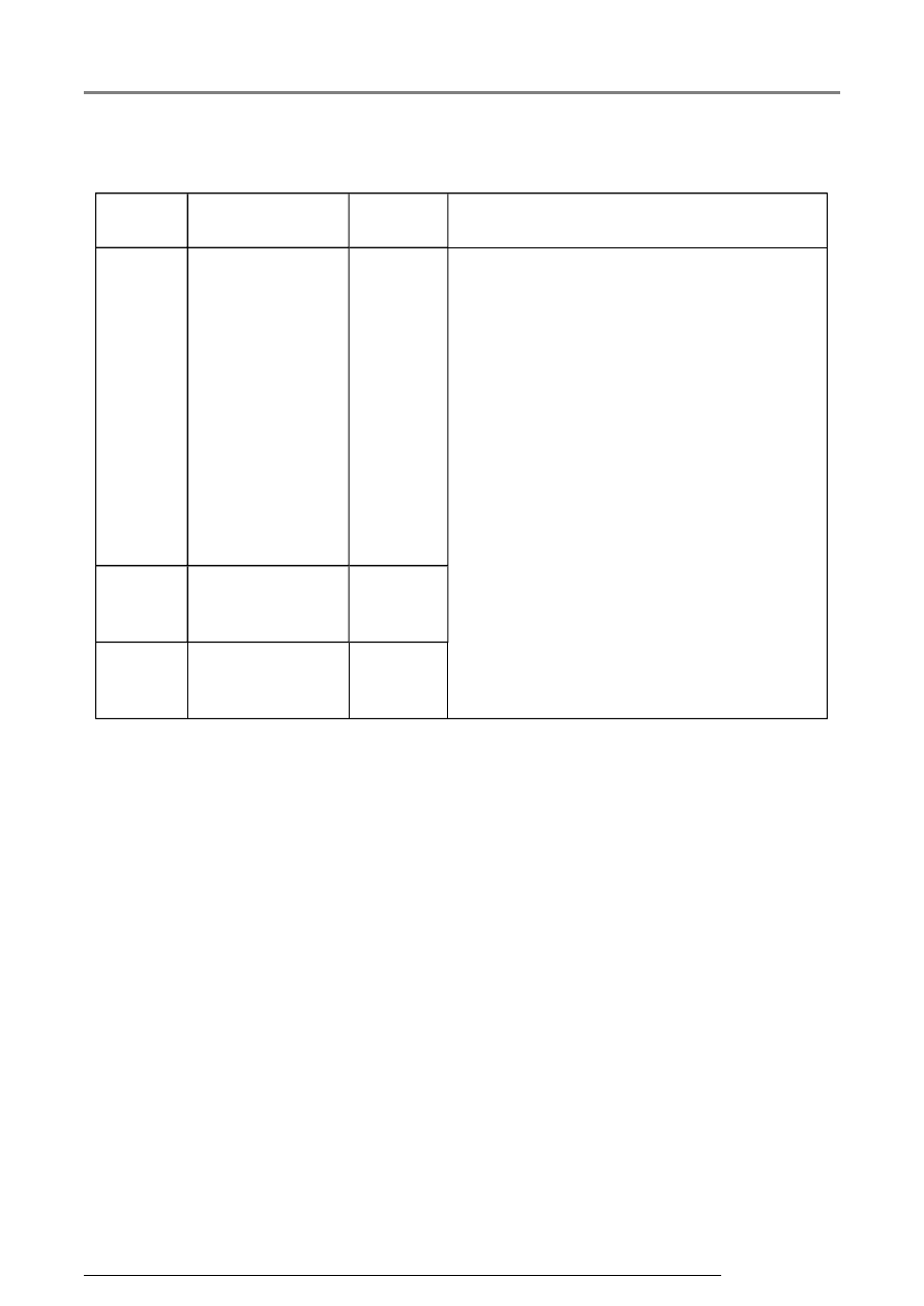
Evaluating display group number 011  

Display 

zone  

Description  

Display  

Corrective action  

1   

Hood contact 
switch  

operated  

not 

operated  

not 

installed  

- Visual check of wiring 

- Check that connections of relevant 
current circuit are correctly connected and 
seated securely while simultaneously 
observing display 

- If the display does not change when 
operating, repair malfunction or replace 
relevant control module 

- Erase DTC memory 

- Perform functional check 

- Check DTC memory again 

2   

Trunk lid/tailgate 
contact switch

3)


open  

closed  


3   

Sliding/tilting roof 
released  

yes  

no  


3)

 Lock rotary latch must be engaged in second stage. 


Convenience system (vehicles with power windows), On Board Diagnostic (O...

13/2/2005

01-190


Break down of display content for display group number 012  

Display group 012 -Central control module-  

Read Measuring Value 
Block 12  


 Indicated on 

display  


xxx  

xxx  

xxx  

xxx     


1  

2  

3  

4  

 Display zones   Specification 

Evaluation 


Optional 
equipment  

Memory / empty

1)


Page 01-

275


Rear equipment  

rl  

rl and rr  

rr  

empty

1)


Front equipment  

driver  

driver and 

passenger  

passenger  

empty

1)


Check bus  

Bus OK.  

Bus not OK.  


1)

 Empty means in this case: Display zone is blank 


Convenience system (vehicles with power windows), On Board Diagnostic (O...

13/2/2005

01-191


Evaluating display group number 012  

Display 

zone  

Description   Display  

Corrective action  

1   

Check bus  

Bus OK.  

Bus not 

OK.  

- Visual check of wiring 

- Check that connections of relevant current 
circuit are correctly connected and seated 
securely while simultaneously observing display 

- If the display does not change when operating, 
repair malfunction or replace relevant 
component 

- If no changes occur, separate all door main 
connectors and reconnect one after the other 
again 

- Observe measured value block 

- If display changes, replace relevant control 
module 

- Erase DTC memory 

- Perform functional check 

- Check DTC memory again 


Continued on next page  

Convenience system (vehicles with power windows), On Board Diagnostic (O...

13/2/2005

01-192


Display 

zone  

Description  

Display  

Corrective action  

2   

Front 
equipment  

driver  

driver and 

passenger  

passenger  

empty

1)


These display zones simply show the 
relevant vehicle equipment 

- For example, checks can be made to 
see which control modules are actively 
connected to the system and which are 
not 

3   

Rear 
equipment  

rl  

rl and rr  

rr  

empty

1)


4   

Optional 
equipment  

memory  

empty

1)


1)

 Empty means in this case: Display zone is blank 


   Example:  


   For DTC "Door control module (DCU), rear 

left not answering" can be directly seen if 
the DCU is connected.   


   For example, only "rr" is shown in display 

zone 3.   

Convenience system (vehicles with power windows), On Board Diagnostic (O...

13/2/2005


Content   ..  851  852  853  854   ..