Volkswagen Golf / Golf GTI / Jetta. Manual - part 405


  Index      Volkswagen     Volkswagen Golf / Golf GTI / Jetta - service repair manual 1999-2005 year


Search            copyright infringement  


Content   ..  403  404  405  406   ..


Volkswagen Golf / Golf GTI / Jetta. Manual - part 405


45-12


-  Remove as much brake fluid as possible from 

brake fluid reservoir using a brake bleeder 
bottle. 


-  Insert brake pedal depressor VAG 1869/2 or 

equivalent. 


-  Activate brake pedal booster with brake pedal 

depressor. 


-  Connect bleeder bottle hose to bleed screw of 

left front brake caliper and open bleed screw.


-  Close left front bleed screw. 


Note:  

Do not let brake fluid enter electrical connectors.

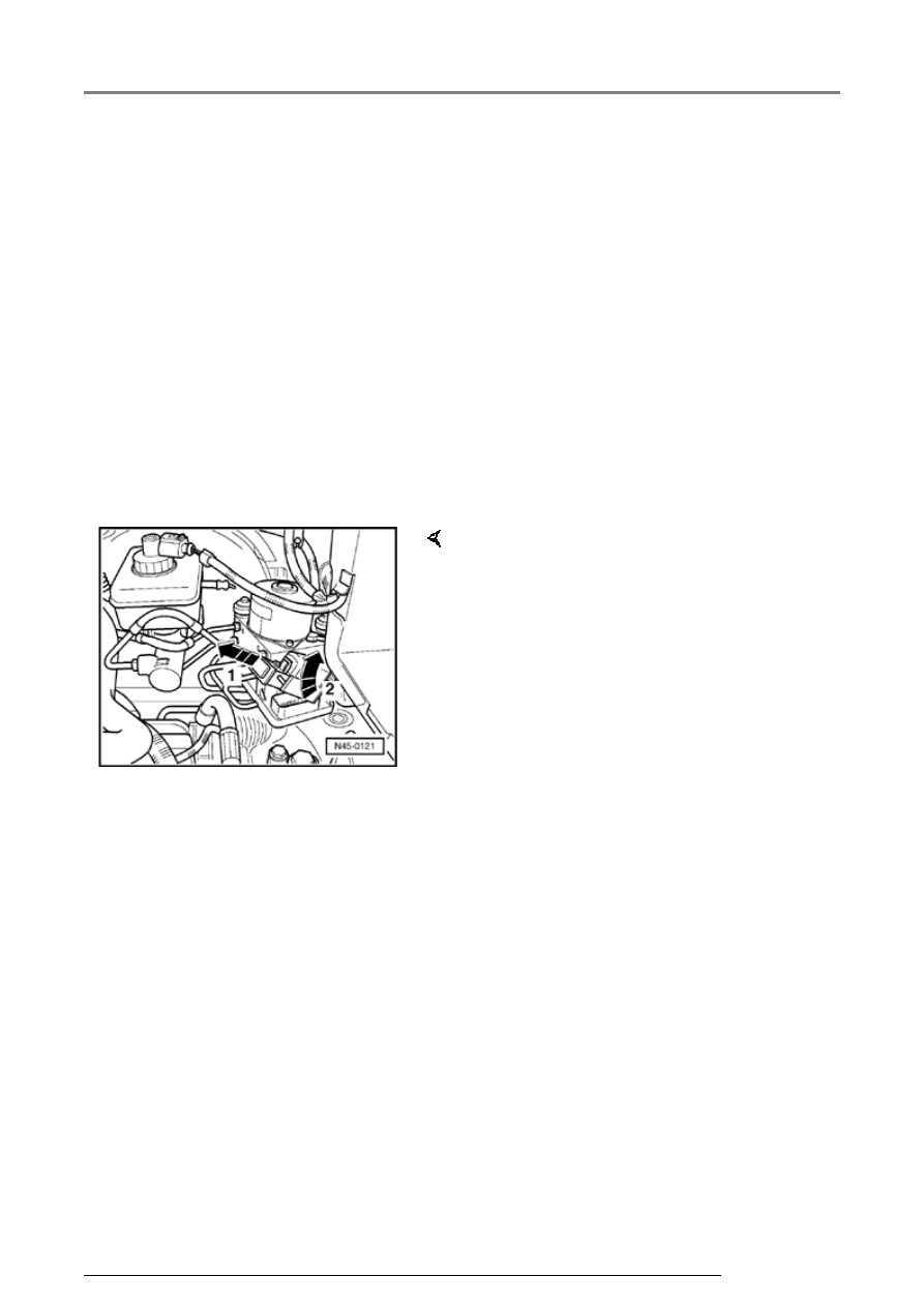
-  Release ABS control module connector (arrow 

1-) and remove (arrow -2-). 

-  Place plastic covering under control module and 

hydraulic unit. Do not use rags. 

Hydraulic unit, brake booster/master cylinder, overview

45-13


-  Disconnect brake lines from 

hydraulic unit to brake master 
cylinder (arrows) and suspend 
with wire. 

-  Disconnect remaining brake lines 

from hydraulic unit. 

-  Seal brake lines and threaded 

holes (arrows) using plugs from 
repair kit, Part No. 1H0 698 311 
A. 


-  Remove bolts from bracket for 

hydraulic unit (arrows). 

-  Remove hydraulic unit with 

control module. 

Hydraulic unit, brake booster/master cylinder, overview

45-14


ABS control module, removing from 
hydraulic unit 


-  Disconnect electrical connector for hydraulic 

pump motor from control module. 


Note:  

-  Remove bolts (arrows) from control module and 

remove control module. 


 When removing the control module make sure 

that the hydraulic unit valve dome does not 
contact the control module solenoid valves.

 Cover the control module magnet coils with a 

plastic cover. Do not use rags. 

 After separating the control module and 

hydraulic unit use transportation protection for 
the valve dome.
 

Hydraulic unit, brake booster/master cylinder, overview

45-15


   Installing  


   Note:  


 Only remove the sealing plugs on the new 

hydraulic unit just before installing the 
corresponding brake line.


 If the sealing plugs are removed from the 

hydraulic unit too early, brake fluid can escape. 
It can then no longer be guaranteed that the 
unit is sufficiently filled or adequately bled.


 When assembling the control module and 

hydraulic unit, be sure that the hydraulic unit 
valve dome does not come in contact with the 
control module solenoid valves.


-  Using new bolts, install control module to 

hydraulic unit. Do not tighten more than max. 4 
Nm (35 in. lb). 


-  Re-connect electrical connector for hydraulic 

pump motor. 


-  Install ABS unit to bracket. 


   Note:  


   Hand-tighten bolts at first to make attaching the 

individual brake lines easier. 


-  After tightening brake lines, tighten hydraulic 

unit. 


-  Continue installation in reverse order of 

removal. 

Hydraulic unit, brake booster/master cylinder, overview


Content   ..  403  404  405  406   ..