Volkswagen Golf / Golf GTI / Jetta. Manual - part 389
01-301
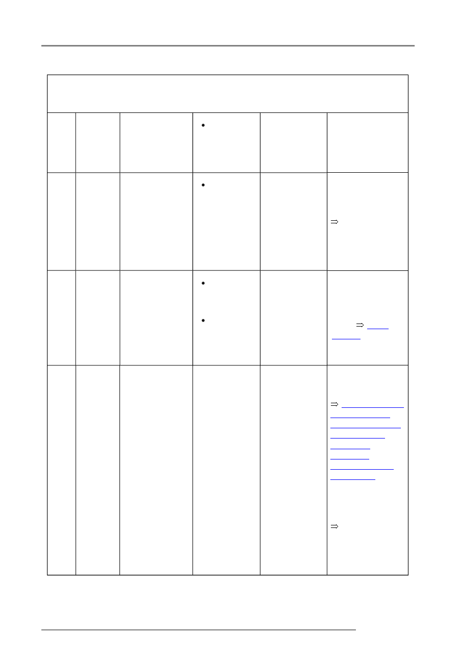
Switch to measuring range:
Voltage measurement (20 V =)
Test
step
V.A.G
1598
sockets
Item tested
Test
conditions
- Additional
operations
Specification Measures for
deviations from
specification
3
4 + 47 Voltage supply
(ignition/starter
switch) to ABS
Control Module
(w/EDL) -J104-
Ignition
switched
on
10.0 - 14.5 V
Electrical
Wiring Diagrams,
Troubleshooting &
Component
Locations binder
- Check wiring
using wiring
diagram
4
47 + 41 Function of
brake light
switch -F-
Ignition
switched
off
Brake
pedal not
depressed
0.0 - 0.5 V
- Check brake
light switch -F-
and read
measured value
block
Page
01-240
, Display
group number
003
- Depress
brake pedal
Approx.
battery
voltage
Repair Manual,
Brake System,
Repair Group 46;
Brake pedal -
Assembly
overview;
Adjusting brake
light switch
Electrical
Wiring Diagrams,
Troubleshooting &
Component
Locations binder
- Adjusting brake
light switch
- Check wiring
using wiring
diagram
Electrical check of Mark 60