Volkswagen Golf / Golf GTI / Jetta. Manual - part 367
01-148
Repair Manual,
Brake System, Repair
Group 45; Removing
and installing parts of
ESP system
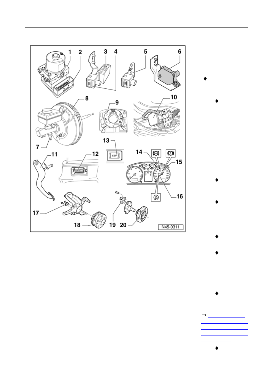
6 - ESP-Sensor
unit -G419-,
vehicles from
02.02
Vehicles with
ABS/EDL/ASR/ESP
only
Combined
sensor for
transverse
acceleration
G200-, sender
for rotation
rate -G202-
and
longitudinal
acceleration
sensor
1)
-
G251-
Assembled
together in one
housing
Checked
electrically by
On Board
Diagnostic
(OBD)
Combined in
one housing
Can be
checked via
read
measured
value block
Page 01-240
Observe
installation
instructions
When the
Electrical/electronic components and installing locations