Volkswagen Golf / Golf GTI / Jetta. Manual - part 242
24-222
If the specifications are not
obtained:
- Remove wiper arms and cowl
panel:
Repair Manual, Electrical
Equipment; Repair Group 92
Electrical Wiring Diagrams,
Troubleshooting & Component
Locations
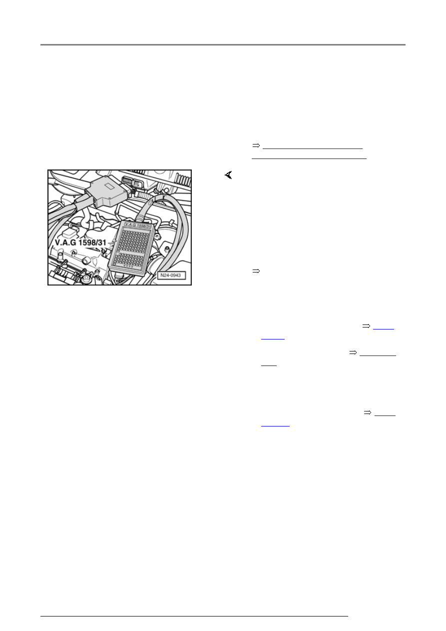
- Connect VAG 1598/31 test box to
control module wiring harness.
Engine Control Module (ECM) -
J220- remains disconnected.
- Check wiring for open/short circuit
from Motronic Engine Control
Module (ECM) -J220- to CCS
operating switch:
- Check DTC memory, repair
malfunctions if necessary and
then erase DTC memory
Page
01-23
.
- Read readiness code
Page 01-
146
. If DTC memory has been
erased or Motronic Engine
Control Module (ECM) -J220- was
disconnected from battery
positive (B+), readiness code
must be generated again
Page
01-149
.
Additional signals, checking