Volkswagen Golf / Golf GTI / Jetta. Manual - part 134


  Index      Volkswagen     Volkswagen Golf / Golf GTI / Jetta - service repair manual 1999-2005 year


Search            copyright infringement  


Content   ..  132  133  134  135   ..


Volkswagen Golf / Golf GTI / Jetta. Manual - part 134


01-115


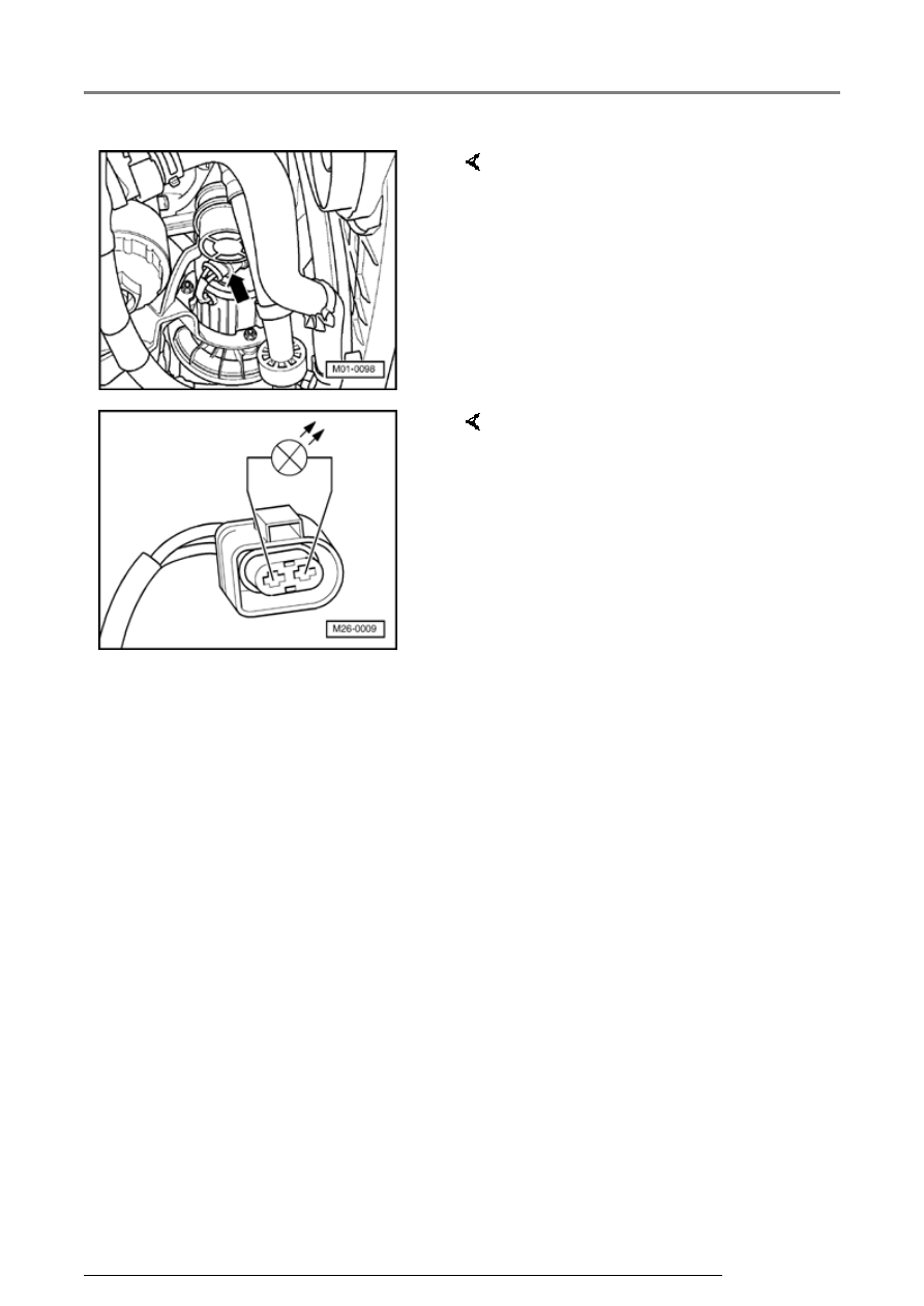
-  Disconnect 2-pin connector from 

Secondary Air Injection (AIR) 
Pump Motor (arrow). 


-  Connect LED test light VAG 1527 

to disconnected connector using 
adapter cables from VAG 1594. 

   LED must flash 

Output Diagnosis Test Mode (DTM)

01-116


LED flashes:  


-  Press -C- button to abort output Diagnosis Test 

Mode (DTM). 

Output Diagnosis Test Mode was aborted

     Indicated on display:  


Repair Manual, 2.8 Liter VR6 4V Engine 

Mechanical, Engine Code(s): BDF; Repair Group 
26


If the LED does not flash but the Secondary Air 
Injection (AIR) Pump Relay clicks: 
 

-  Switch off ignition. 

-  Replace Secondary Air Injection (AIR) Pump 

Motor -V101-: 

-  Check DTC memory, repair Diagnostic Trouble 

Codes (DTCs) if necessary and then erase DTC 
memory 


Page 01-23

 , DTC memory, checking 

and erasing. 

-  Read readiness code 


Page 01-146

 . If the 

DTC memory has been erased or the Motronic 
Engine Control Module (ECM) -J220- was 
disconnected from battery (B+) positive, the 
readiness code must be generated again 


Page 01-149

 . 

-  Press -C- button to abort Output Diagnosis Test 

Mode (DTM). 

Output Diagnosis Test Mode was aborted

     Indicated on display:  

-  Switch off ignition. 

Output Diagnosis Test Mode (DTM)

01-117


If no electrical or wiring concerns are 
found:  

-  Check wire for open circuit 

between Secondary Air Injection 
(AIR) pump motor -V101- terminal 
1 and body Ground (GND). 

   Wire resistance: max. 1.5 


Note: 

-  Pull Secondary Air Injection (AIR) 

Pump Relay -1- out of relay 
carrier in protective housing for 
control modules. 

 If tools are necessary to pull 

relays or control modules out of 
the relay plate, first disconnect 
battery Ground (GND) strap.
 

 Before disconnecting battery 

Ground (GND) strap obtain code 
for radios with anti-theft coding.
 

Output Diagnosis Test Mode (DTM)

01-118


If no electrical or wiring concerns are 
found:  

-  Check wiring for open circuit 

between connector terminal 2 on 
Secondary Air Injection (AIR) 
Pump Motor and terminal 2 on 
relay plate. 

-  Wire resistance: max. 1.5 


If no electrical or wiring concerns are 
found:  

-  Check wire for open circuit 

between terminal 1 of relay plate 
and fuel pump (FP) relay -J17- 
referring to Electrical Wiring 
Diagrams. 

   Wire resistance: max. 1.5 


-  Replace Secondary Air Injection 

(AIR) pump relay -J299-. 

-  Check DTC memory, repair 

Diagnostic Trouble Codes (DTCs) 
if necessary and then erase DTC 
memory 


Page 01-23

 , DTC 

memory, checking and erasing. 

Output Diagnosis Test Mode (DTM)


Content   ..  132  133  134  135   ..