содержание .. 912 913 914 915 ..
Toyota Sequoia (2005). Manual - part 914
H16749
H18899
H24373
4 Claws
H16751
2 Clips
H21029
BO–92
–
BODY
INSTRUMENT PANEL
3645
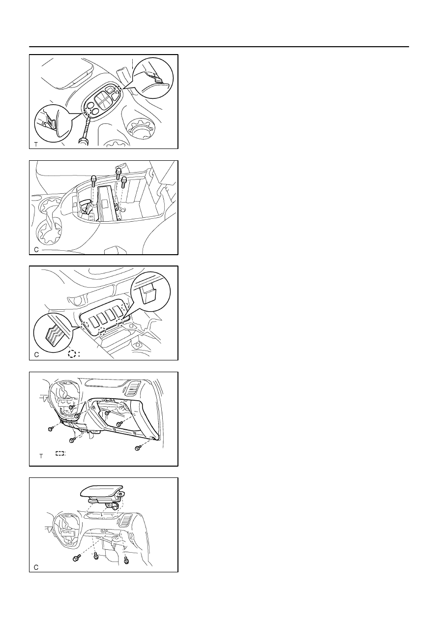
24.
REMOVE REAR CONSOLE BOX
(a)
w/ Rear heater A/C:
Using a screwdriver, remove the rear heater control pan-
el, then disconnect the connector.
HINT:
Tape the screwdriver tip before use.
(b)
w/ Headphone terminal.
Using a screwdriver, remove the headphone terminal and
the connector.
(c)
w/ Rear seat entertainment:
(1)
Remove the disc bracket.
(2)
Remove the 3 bolts and disc player.
(3)
Disconnect the connector.
(d)
Remove the 4 bolts and rear console box.
25.
REMOVE CONSOLE BOX BEZEL
(a)
Using a screwdriver, remove the console box bezel.
HINT:
Tape the screwdriver tip before use.
(b)
Disconnect the connectors.
26.
REMOVE FRONT CONSOLE BOX
Remove the 2 bolts, 2 clips and front console box.
27.
REMOVE LOWER INSTRUMENT COVER
(a)
Remove the 4 bolts and 3 screws.
(b)
Using a screwdriver, remove the lower instrument cover.
HINT:
Tape the screwdriver tip before use.
28.
REMOVE PASSENGER AIRBAG ASSEMBLY
(a)
Remove the 2 bolts holding the front passenger airbag
assembly and instrument panel.
Torque: 5.0 N·m (51 kgf·cm, 44 in.·lbf)