содержание .. 524 525 526 527 ..
Toyota Sequoia (2005). Manual - part 526
I18627
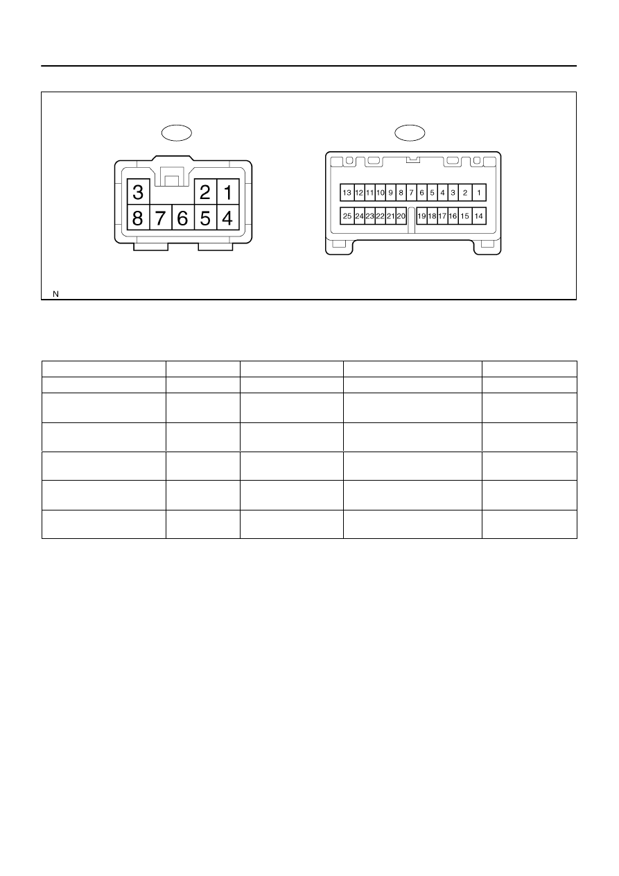
B11
B10
–
DIAGNOSTICS
MULTIPLEX COMMUNICATION SYSTEM
DI–1899
2093
5.
CHECK BACK DOOR ECU
(a)
Disconnect the B10 and B11 ECU connectors.
(b)
Measure the resistance or voltage of each terminal of the wire harness side connector.
Standard:
Symbols (Terminals No.)
Wiring Color
Terminal Description
Condition
Specified Condition
MPX2 (B11–1) – Body ground
B – Body ground
MPX line
Always
10 k
Ω
or higher
MPX1 (B11–2) – Body ground
LG–R –
Body ground
MPX line
Always
10 k
Ω
or higher
GND (B11–3) – Body ground
W–B –
Body ground
Ground
Always
Below 1
Ω
BDR (B11–4) – Body ground
L–W –
Body ground
+B (BATT) power supply
Always
10 to 14 V
BECU (B11–5) – Body ground
W–R –
Body ground
+B (BATT) power supply
Always
10 to 14 V
SIG (B11–6) – Body ground
B–R –
Body ground
Ignition power supply
Ignition switch ON
10 to 14 V
If the result is not as specified, there may be a malfunction on the wire harness side.