содержание .. 458 459 460 461 ..
Toyota Sequoia (2005). Manual - part 460
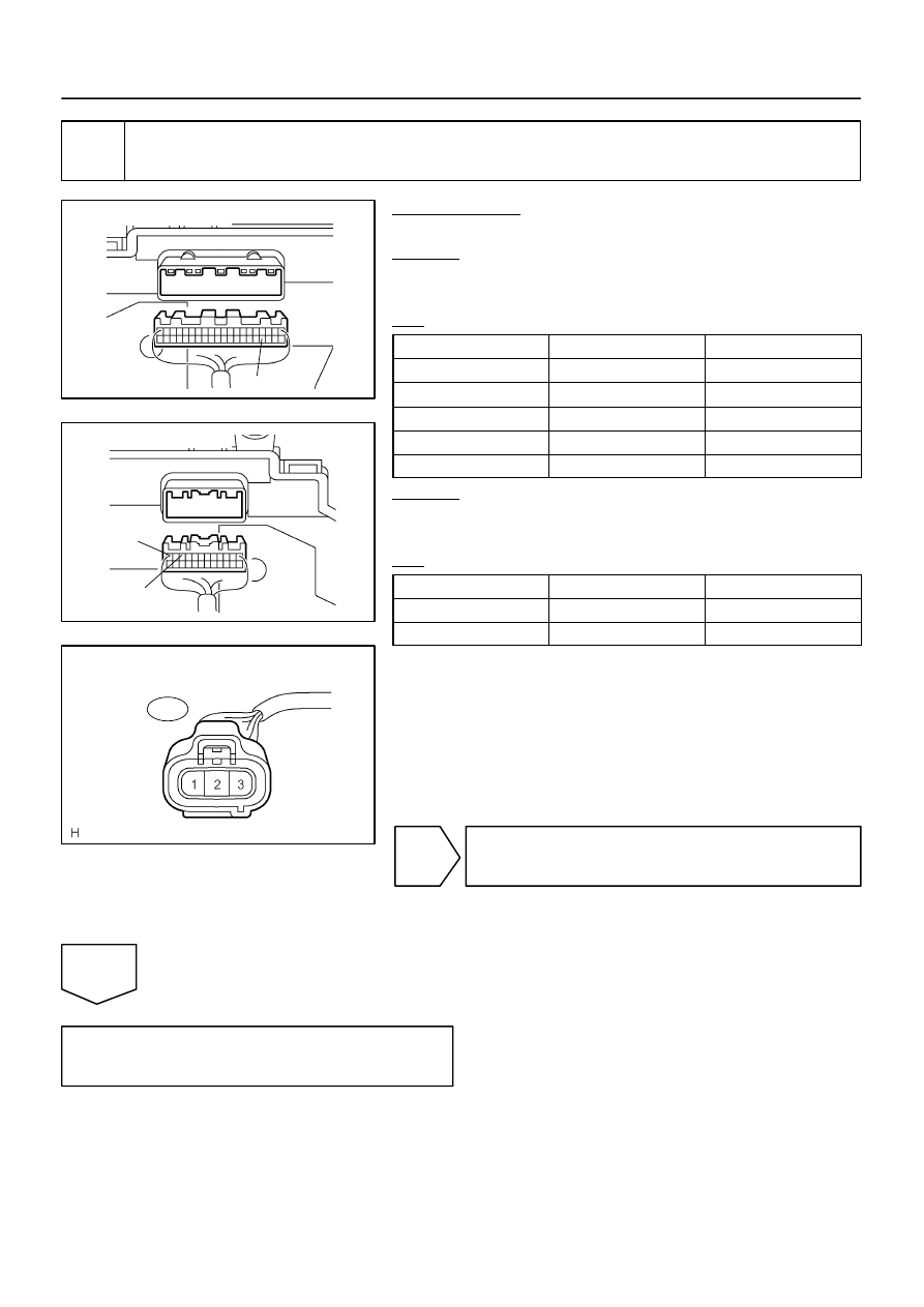
I28569
Combination Meter:
C5–24
I28570
Combination Meter:
C6–12
C6–10
I28573
Vehicle Speed Sensor
Wire Harness Side:
V1
–
DIAGNOSTICS
COMBINATION METER SYSTEM
DI–1635
1829
4
Check harness and connector (Vehicle speed sensor – combination meter and
vehicle speed sensor – battery).
PREPARATION:
Disconnect the combination meter connector.
CHECK:
Measure the resistance according to the value(s) in the table
below.
OK:
Tester connection
Condition
Specified condition
C5–24 – V1–3
Always
Below 1
Ω
C6–10 – V1–2
Always
Below 1
Ω
C6–12 – Body ground
Always
Below 1
Ω
C5–24 – Body ground
Always
10 k
Ω
or higher
C6–10 – Body ground
Always
10 k
Ω
or higher
CHECK:
Measure the voltage according to the value(s) in the table be-
low.
OK:
Tester connection
Condition
Specified condition
V1–1 – Body ground
Ignition switch OFF
Below 1 V
V1–1 – Body ground
Ignition switch ON
10 to 14 V
NG
Repair or replace harness or connector.
OK
Replace combination meter
(See page
).