содержание .. 455 456 457 458 ..
Toyota Sequoia (2005). Manual - part 457
I27707
C6–21
C6–8
(*4) C5–15
C5–18
C5–2
C5–14
C5–19
C5–13
C6–1
C6–2
C6–3
C5–20
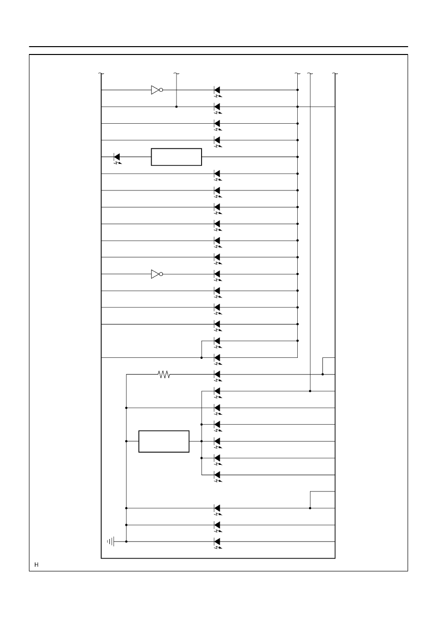
ABS
CHARGE
A/T OIL TEMP
CHECK E/G
4LO
O/D OFF
A/T L
WASHER
SLIP
VSC OFF
VSC TRAC
4HI
CRUISE
ONE STEP
DIMMER
C6–24
C6–5
C6–6
C6–4
C5–40
TIRE PRS
CTR DIFF LOCK
RSCA OFF
SECURITY
P
R
N
C5–16
C5–17
C5–34
C5–35
C5–36
C5–37
C5–38
C5–39
C6–17 (*5)
C6–18 (*6)
C5–33
C6–19
TURN (L)
TURN (R)
BEAM
3
2
D
*4: 4WD *5: w/o Daytime Running Light *6: w/ Daytime Running Light
ONE STEP
DIMMER
RSCA OFF
–
DIAGNOSTICS
COMBINATION METER SYSTEM
DI–1623
1817