содержание .. 393 394 395 396 ..
Toyota Sequoia (2005). Manual - part 395
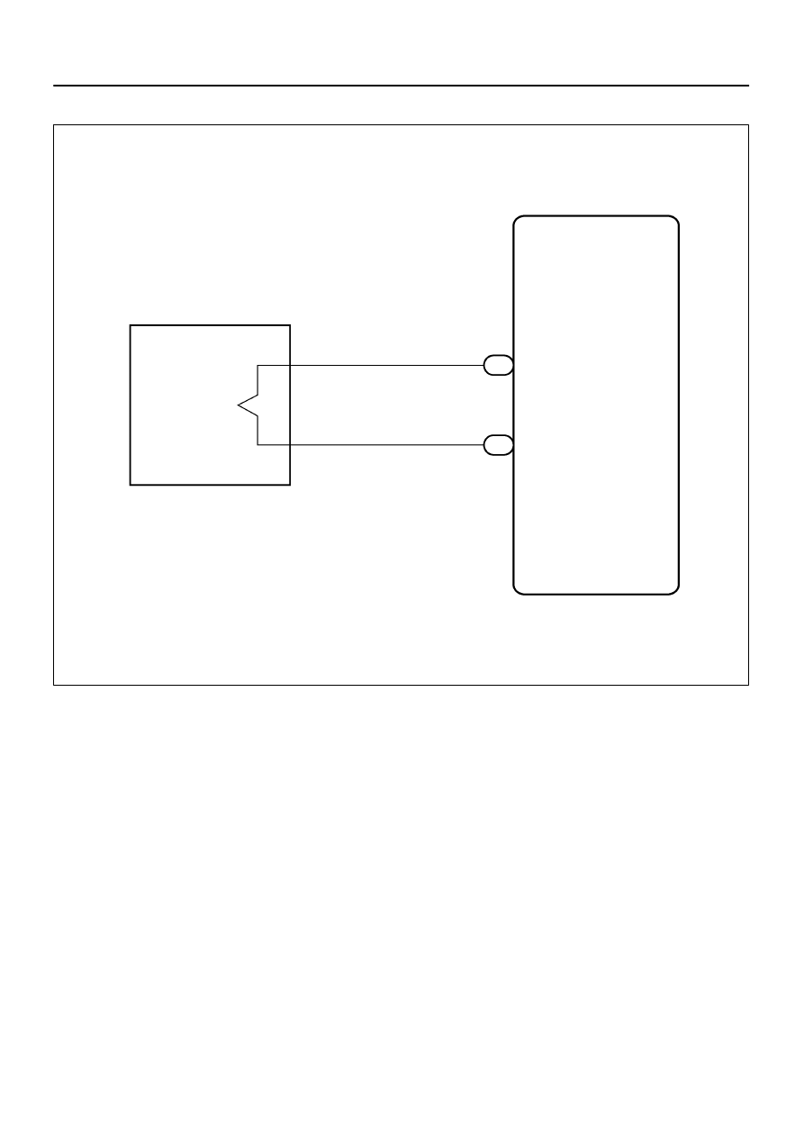
H01454
Airbag Sensor Assembly
A20 P+
4
Y–B
A22
P Squib
A20 P–
3
Y
1
2
–
DIAGNOSTICS
SUPPLEMENTAL RESTRAINT SYSTEM
DI–1375
1569
WIRING DIAGRAM
Главная Automobile - Toyota Toyota Sequoia - Repair manual 2005 year
поиск по сайту правообладателям
|
|
|
содержание .. 393 394 395 396 ..
H01454 Airbag Sensor Assembly A20 P+ 4 Y–B A22 A20 P– 3 Y 1 2 – DIAGNOSTICS SUPPLEMENTAL RESTRAINT SYSTEM DI–1375 1569 WIRING DIAGRAM |