содержание .. 121 122 123 124 ..
Toyota Sequoia (2005). Manual - part 123
B17447
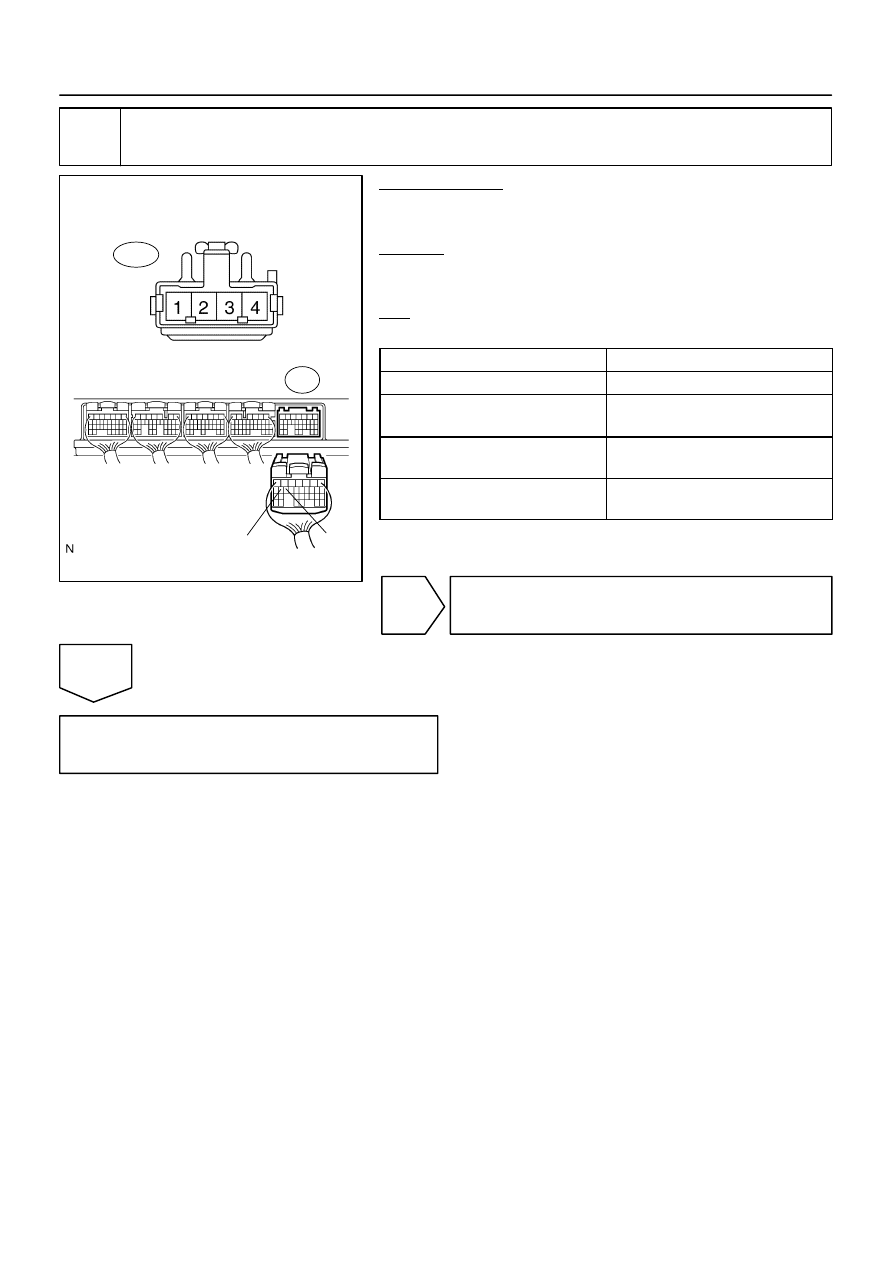
Wire Harness Side:
Stop Light Switch Connector
S14
ST1–
STP
E4
–
DIAGNOSTICS
ENGINE
DI–287
481
4
Check harness and connector between ECM and stop light switch.
PREPARATION:
(a)
Disconnect the S14 stop light switch connector.
(b)
Disconnect the E4 ECM connector.
CHECK:
Measure the resistance between the wire harness side connec-
tors.
OK:
Standard:
Tester Connection
Specified Condition
Stop light switch (S14–1) – STP (E4–15)
Below 1
Ω
Stop light switch (S14–3) – ST1–
(E4–16)
Below 1
Ω
Stop light switch (S14–1) or
STP (E4–15) – Body ground
10 k
Ω
or higher
Stop light switch (S14–3) or
ST1– (E4–16) – Body ground
10 k
Ω
or higher
NG
Repair or replace harness or connector.
OK
Replace ECM (See page