Suzuki Grand Vitara JB419. Manual - part 57
Engine Lubrication System: 1E-8
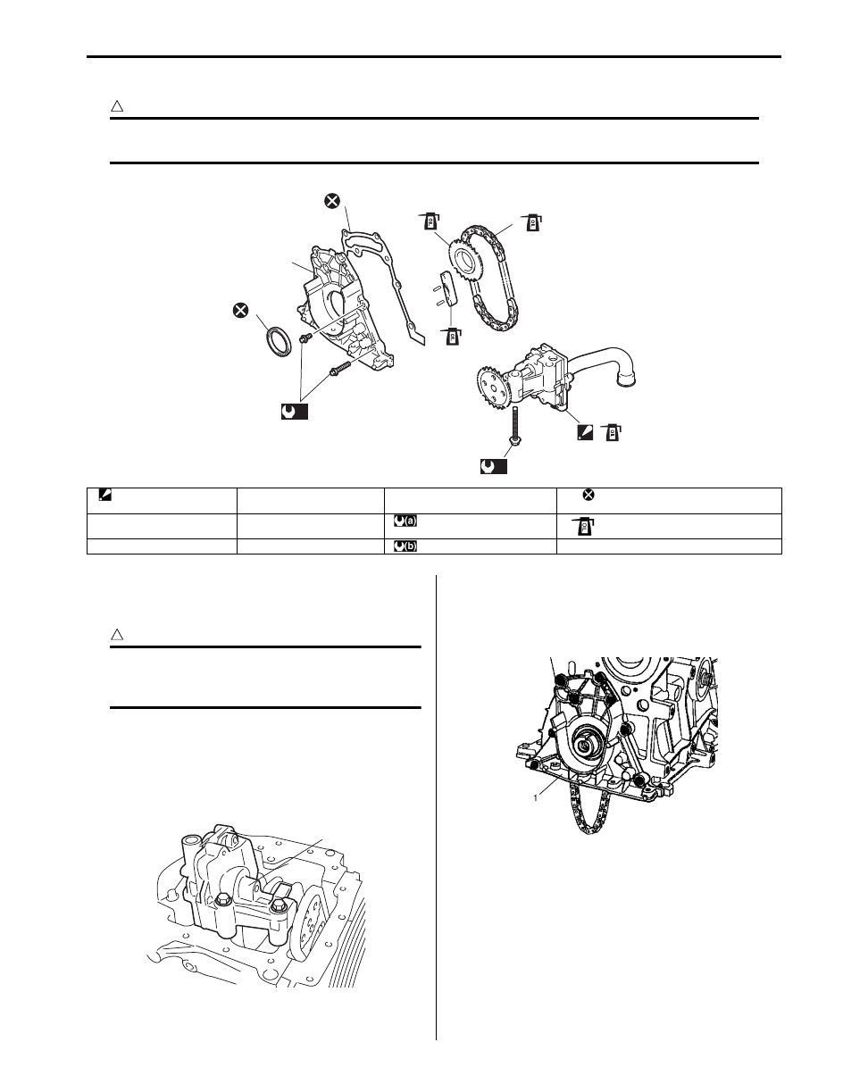
Oil Pump, Oil Pump Chain and Gasket Holder Plate Component
S5JB0B1506003
CAUTION
!
Never disassemble oil pump. Disassembly will spoil its original function. If faulty condition is found,
replace it with new one.
Oil Pump, Oil Pump Chain and Gasket Holder
Plate Removal and Installation
S5JB0B1506004
CAUTION
!
Never disassemble oil pump. Disassembly
will spoil its original function. If faulty
condition is found, replace it with new one.
Removal
1) Remove oil pan and oil pump strainer referring to “Oil
Pan and Oil Pump Strainer Removal and
Installation”.
2) Remove oil pump (1) from cylinder block.
3) Remove timing belt and crankshaft timing pulley
referring to “Timing Belt and Belt Tensioner Removal
and Installation in Section 1D”.
4) Remove gasket holder plate (1) from cylinder block.
4
(a)
(b)
6
1
5
7
2
3
I5JB0B150043-01
1. Oil pump
: Do not disassemble.
4. Gasket holder plate
7. Oil pump chain tensioner
: Do not reuse.
2. Oil pump drive sprocket
5. Gasket holder plate gasket
: 24 N
⋅m (2.4 kgf-m, 17.5 lb-ft)
: Apply engine oil to sliding surface of
each part.
3. Oil pump chain
6. Crankshaft oil seal
: 14 N
⋅m (1.4 kgf-m, 10.5 lb-ft)
1
I5JB0B150030-01
I5JB0B150031-01