Suzuki Grand Vitara JB416 / JB420. Manual - part 395


  Index      Suzuki     Suzuki Grand Vitara JB416 / JB420- service repair manual


Search            


Content   ..  393  394  395  396   ..


Suzuki Grand Vitara JB416 / JB420. Manual - part 395


9J-1 Hood / Fenders / Doors: 

Body, Cab and Accessories

Hood / Fenders / Doors

Repair Instructions

Hood Removal and Installation

S5JB0A9A06001

Removal

CAUTION

!


Place cloth to prevent body from any 
damage.


1) Remove hood silencer (4).
2) Disconnect window washer hose (1) from hood.
3) Remove 4 mounting bolts (3) to detach hood (2).

Installation
Reverse removal procedure noting the following.
• Apply sealant to contact face “A” of hood hinge.

“A”:  Sealant 99000–31110 (SUZUKI Bond 
No.1215)

• Adjust hood lock position if necessary referring to 

“Hood Inspection and Adjustment”.

Hood Inspection and Adjustment

S5JB0A9A06002

Inspection
• Check that hood opens and closes smoothly and 

properly. Lubricate if necessary.

• Check that hood stops in the secondary latched 

position properly (preventing hood from opening 
freely) and that hood closes completely in the fully 
latched position.

• Adjust hood lock position, if necessary.

Adjustment
Adjust the following point:
• Hood position adjustment.

Fore-and-aft and right-and-left adjustment.
Adjust hood clearance by loosening hood mounting 
bolts. Refer to “Panel Clearance in Section 9K”.

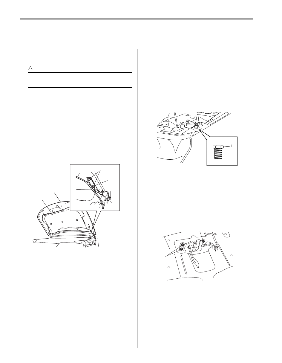
• Vertical adjustment

If only one side (right or left) of hood is not level with 
front fender, make it level by tightening or loosening 
hood cushion (1).

• Hood lock position adjustment

a. Loosen hood lock bolts.
b. Adjust hood lock height position so the hood is 

locked without looseness.

c. Tighten hood latch bolts to specified torque.

Tightening torque
Hood latch bolt (a):  10 N·m (1.0 kgf-m, 7.5 lb-
ft)

d. Make sure the hood is locked smoothly and 

securely.

4

2

1

3

“A”

“A”

I5JB0A9A0001-01

I5JB0A9A0002-01

(a)

(a)

I5JB0A9A0003-01

Hood / Fenders / Doors:  9J-2

Front Fender Components

S5JB0A9A06003

Front Fender Removal and Installation

S5JB0A9A06004

Removal

1) Remove splash guard (if equipped) referring to “Splash Guard Removal and Installation (If Equipped) in Section 

9M”.

2) Remove front fender lining.
3) Remove front bumper referring to “Front Bumper Components in Section 9K”.
4) Remove headlight assembly referring to “Headlight Housing Removal and Installation in Section 9B”.
5) Remove cowl top garnishes referring to “Cowl Top Components in Section 9K”
6) Disconnect connector from side turn signal lamp.
7) Remove front fender.

Installation
Reverse removal procedure to install front fender noting the following instruction. 
• If paint on fender bolt is peeled off, be sure to apply paint again.
• Adjust panel clearance referring to “Panel Clearance in Section 9K”.

1

3

2

4

I5JB0A9A0004-02

1. Front fender lining

3. Front fender rear pad

2. Front fender

4. Splash guard (if equipped)

9J-3 Hood / Fenders / Doors: 

Front Door Assembly Components

S5JB0A9A06005

2

2

1

(a)

4

(a)

4

(a)

5

3

(b)

7

(b)

(b)

7

6

I5JB0A9A0005-01

1. Door panel

5. Door open stopper bolt

: 23 N

⋅m (2.3 kgf-m, 17.0 lb-ft)


 2. Door hinge

: Apply lithium grease 99000-25010 to rotating part.
: Apply sealant 99000-31110 to contact face.

6. Front door opening weather-strip

3. Door open stopper

7. Front door hinge bolt (door side)

4. Front door hinge bolt (body side)

: 27 N

⋅m (2.7 kgf-m, 19.5 lb-ft)

Hood / Fenders / Doors:  9J-4

Front Door Assembly Removal and Installation

S5JB0A9A06006

Removal

1) Remove front fender referring to “Front Fender 

Components”.

2) Disconnect door harness lead wires at each coupler.
3) Remove door open stopper (1).

4) Support door panel (1) using a jack (2) with rags (3) 

and a piece of wood (4) placed between jack (2) and 
panel (1) as shown.

5) Remove door assembly (1) by loosening hinge 

mounting bolts (2).

Installation
Reverse removal procedure to install door assembly 
noting the following instructions.
• When replacing door, coat replacement door inside 

with wax for proper anti-corrosion treatment. Refer to 
“Sealant Application Areas in Section 9L”.

• Apply sealant to contact face “A” of hinge (1) and 

apply grease to rotating part “B” of hinge (1).

“A”:  Sealant 99000–31110 (SUZUKI Bond 
No.1215)
“B”:  Grease 99000–25010 (SUZUKI Super Grease 
A)

• Tighten hinge bolt to specified torque.

Tightening torque
Door hinge mounting bolt (body side) (a):  27 N·m 
(2.7 kgf-m, 19.5 lb-ft)
Door hinge mounting bolt (door side) (b):  23 N·m 
(2.3 kgf-m, 17.0 lb-ft)

• When door open stopper (1) is installed, make sure 

punch mark (2) is upward.

Door open stopper installing direction
Left side door: L punch mark is upward
Right side door: R punch mark is upward

• Tighten door open stopper bolt (3) to specified torque.

Tightening torque
Door open stopper bolt (a):  27 N·m (2.7 kgf-m, 
19.5 lb-ft)

• Adjust door latch striker position referring to “Front 

Door Lock Assembly Removal and Installation in 
Section 9F”.

• Adjust front door cushion so that door becomes flush 

with side body.

• After installation, open and close the door to check 

looseness. 

I4RS0A9A0005-01

I2RH019A0003-01

2

1

I5JB0A9A0006-01

1

(a)

(b)

(b)

“A”

“A”

“B”

I5JB0A9A0007-01

I4RS0A9A0008-01


Content   ..  393  394  395  396   ..