Suzuki Grand Vitara JB416 / JB420. Manual - part 375


  Index      Suzuki     Suzuki Grand Vitara JB416 / JB420- service repair manual


Search            


Content   ..  373  374  375  376   ..


Suzuki Grand Vitara JB416 / JB420. Manual - part 375


9C-9 Instrumentation / Driver Info. / Horn: 

Warning Buzzer Circuit Symptom Diagnosis

S5JB0A9304012

NOTE

• Use of SUZUKI scan tool makes it easy to check whether a faulty condition is on the input side or 

output side of BCM. For checking procedure, refer to “Diagnosis Using Output Test Function of 
SUZUKI Scan Tool” under “Scan Tool Data in Section 10B”.

• Check each part in the order from the top of the following list.


Cigarette Lighter Symptom Diagnosis (If Equipped)

S5JB0A9304013

Horn Symptom Diagnosis

S5JB0A9304014

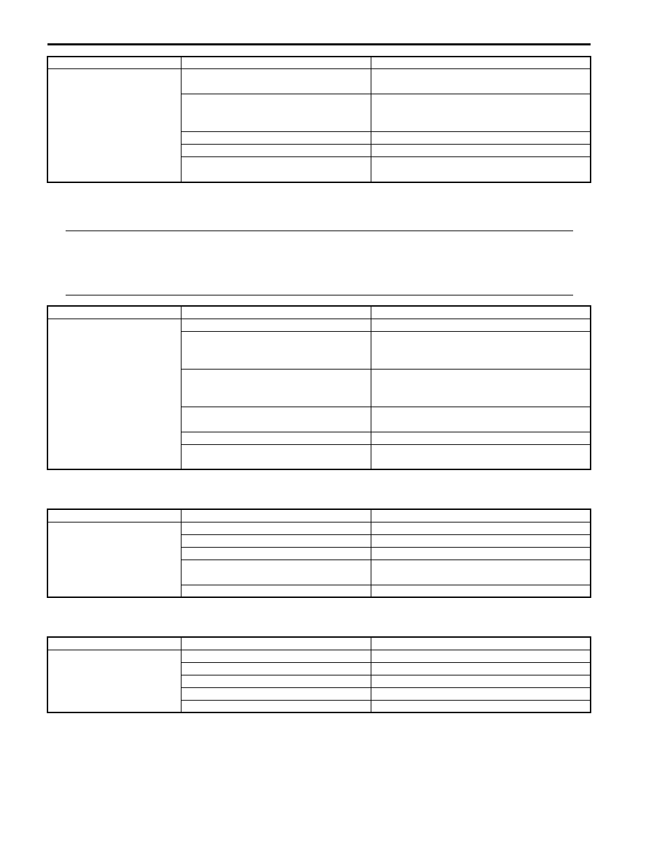
Main beam (high beam) 
indicator stay ON

Data (information) can not be received 
by CAN communication

Check BCM for DTC referring to “DTC Check 
in Section 10B”.

Combination switch faulty

Check combination switch referring to 
“Headlight Switch (in Lighting Switch) 
Inspection in Section 9B”.

Wiring or ground faulty

Repair circuit.

Combination meter faulty

Replace combination meter.

BCM faulty

Replace after making sure that none of above 
parts is faulty.

Condition

Possible cause

Correction / Reference Item

Condition

Possible cause

Correction / Reference Item

Warning buzzer shows no 
sounding

Circuit fuse blown

Replace fuse and check for short circuit.

Driver side door switch faulty

Check driver side door switch referring to 
“Door Switch (Front / Rear / Rear End Door) 
Inspection”.

Lighting switch faulty

Check lighting switch referring to “Headlight 
Switch (in Lighting Switch) Inspection in 
Section 9B”
.

Key remainder switch faulty

Check key remainder switch referring to 
“Ignition Switch Inspection”.

Wiring or ground faulty

Repair circuit.

BCM faulty

Replace after making sure that none of above 
parts is faulty.

Condition

Possible cause

Correction / Reference Item

Cigarette lighter shows 
no operation

Circuit fuse blown

Replace fuse and check for short circuit.

ACC relay faulty

Replace relay

Cigarette lighter faulty

Check cigarette lighter.

Ignition switch faulty

Check ignition switch referring to “Ignition 
Switch Inspection”.

Wiring or grounding faulty

Repair circuit.

Condition

Possible cause

Correction / Reference Item

Horn does not operate

Circuit fuse blown

Replace fuse and check for short circuit.

Horn switch faulty

Check horn switch.

Horn relay faulty

Check horn relay.

Wiring or grounding faulty

Repair circuit.

Horn faulty

Replace horn.

Instrumentation / Driver Info. / Horn:  9C-10

Information Display Symptom Diagnosis (If Equipped)

S5JB0A9304015

NOTE
This thermometer indicates the ambient temperature in back of front bumper member. Under any one 
of the following listed conditions, however, even when the ambient temperature goes up, the 
thermometer display does not rise so as to correct the rise of the ambient temperature caused by the 
radiant heat of the engine. When the ambient temperature drops, the thermometer reading follows the 
change in the temperature.
Be sure to bear this in mind when diagnosing trouble.
• The vehicle speed is 30 km/h (18 mph) or lower.
• VSS signal is faulty.
• The ignition switch is turned on again within 2 hours.


Clock Symptom Diagnosis (If Equipped)

S5JB0A9304020

Condition

Possible cause

Correction / Reference Item

No displaying of 
information display

Circuit fuse Blown

Replace fuse and check for short circuit.

Wiring and/or grounding faulty

Repair as necessary.

Information display unit faulty

Replace unit.

Incorrect thermometer 
display

Outside air temperature sensor faulty

Check outside air temperature sensor referring 
to “Outside Air Temperature Sensor Inspection 
(If Equipped)”.

Vehicle speed signal faulty

Check ECM for DTC referring to “DTC Check 
in Section 1A”.

Wiring and/or grounding faulty

Repair as necessary.

BCM faulty

Replace after making sure that none of above 
parts is faulty.

Display does not change 
at –30 

°

C

Outside air temperature is –30 

°C (–22 

°F) or less

Outside air temperature sensor faulty

Check outside air temperature sensor referring 
to “Outside Air Temperature Sensor Inspection 
(If Equipped)”.

Outside air temperature sensor wiring 
circuit open circuit and/or short to power 
circuit

Repair as necessary.

BCM faulty

Replace after making sure that none of above 
parts is faulty.

Display does not change 
at 50

°

C

Outside air temperature is 50 

°C (122 

°F) or more

Outside air temperature sensor faulty

Check outside air temperature sensor referring 
to “Outside Air Temperature Sensor Inspection 
(If Equipped)”.

Outside air temperature sensor wiring 
circuit short to ground circuit

Repair as necessary.

BCM faulty

Replace after making sure that none of above 
parts is faulty.

Condition

Possible cause

Correction / Reference Item

No displaying of clock

Circuit fuse Blown

Replace fuse and check for short circuit.

Wiring and/or grounding faulty

Repair as necessary.

Clock unit faulty

Replace unit.

9C-11 Instrumentation / Driver Info. / Horn: 

Audio System Symptom Diagnosis (If Equipped)

S5JB0A9304016

Radio

NOTE
Electronic part / system with undiagnosed problem may cause electromagnetic interference. 
Electromagnetic interference condition may have poor radio reception. To test for presence of 
electromagnetic interference in part / system, perform the following procedures.
1. Turn ignition switch to OFF.
2. Systematically disconnect the electronic part / system connector(s) one at a time.
3. Turn ignition switch to ON.
4. Check any improvement in radio reception.


CD Player

Condition

Possible cause

Correction / Reference Item

Poor radio reception

Out of service area (Poor location)

Antenna faulty

Replace antenna.

Antenna amplifier faulty

Replace antenna amplifier.

Electrical part / system faulty

Repair or replace electrical part / system 
referring to after-mentioned NOTE.

Wiring and/or grounding faulty

Repair as necessary.

Radio assembly faulty

Replace radio assembly.

Radio does not operate 
and speaker does not 
sound

Circuit fuse(s) blown

Replace fuse(s) and check for short circuit.

Wiring and/or grounding faulty

Repair as necessary.

Radio assembly faulty

Replace radio assembly.

Radio does not operate, 
but speaker sound

Wiring and/or grounding faulty

Repair as necessary.

Radio assembly faulty

Replace radio assembly.

Radio is operative, but all 
speakers does not sound

Wiring and/or grounding faulty

Repair as necessary.

Radio assembly faulty

Replace radio assembly.

Individual speaker is 
noisy or inoperative

Wiring and/or grounding faulty

Repair as necessary.

Speaker faulty

Replace speaker.

Radio assembly faulty

Replace radio assembly.

Sound quality is poor

Out of service area (Poor location)

Speaker installed incorrectly

Install correctly.

Wiring and/or grounding faulty

Repair as necessary.

Speaker faulty

Replace speaker.

Radio assembly faulty

Replace radio assembly.

Condition

Possible cause

Correction / Reference Item

CD-ROM does not insert

Another CD-ROM already inserted

Eject CD-ROM.

Circuit fuse blown

Replace fuse and check for short circuit.

Wiring and/or grounding faulty

Repair as necessary.

Extraneous material come to be mixed 
CD player

Clear extraneous material from CD player or 
replace radio assembly.

Radio assembly faulty

Replace radio assembly.

CD-ROM does not eject

Circuit fuse blown

Replace fuse and check for short circuit.

Wiring and/or grounding faulty

Repair as necessary.

Extraneous material come to be mixed 
in CD player

Clear extraneous material from CD player or 
replace radio assembly.

Radio assembly faulty

Replace radio assembly.

CD player does not load 
CD-ROM

CD-ROM faulty

CD-ROM inserted with incorrect side up Insert correctly.
Temperature in cabin is too hot

Water droplets form on internal lens

Dry about 1 hour with power on.

Radio assembly faulty

Replace radio assembly.

Instrumentation / Driver Info. / Horn:  9C-12

Remote Audio Control Switch Symptom Diagnosis (If Equipped)

S5JB0A9304017

Navigation Symptom Diagnosis (If Equipped)

S5JB0A9304021

Repair Instructions

Ignition Switch Removal and Installation

S5JB0A9306001

Removal

1) Disconnect negative cable at battery.
2) Confirm that ignition key is removed.
3) Remove steering column hole cover (1).
4) Turn steering wheel to remove steering column 

cover screws (3) and then remove steering column 
covers (2).

5) Disconnect couplers (1) from ignition switch (2).
6) Remove ignition switch (2) from key cylinder (3).

Installation
Reverse removal procedure.

Sound skips or is noisy

CD-ROM faulty

Driving vibration

Water droplets form on internal lens

Dry about 1 hour with power on.

Radio assembly installed incorrectly

Install correctly.

Radio assembly faulty

Replace radio assembly.

CD player is operative, 
but all speakers does not 
sound

Wiring and/or grounding faulty

Repair as necessary.

Radio assembly faulty

Replace radio assembly.

Individual speaker is 
noisy or inoperative

Wiring and/or grounding faulty

Repair as necessary.

Speaker faulty

Replace speaker.

Radio assembly faulty

Replace radio assembly.

Sound quality or volume 
is poor

CD-ROM faulty

Wiring and/or grounding faulty

Repair as necessary.

Speaker installed incorrectly

Install correctly.

Speaker faulty

Replace speaker.

Condition

Possible cause

Correction / Reference Item

Condition

Possible cause

Correction / Reference Item

Audio system is 
operative, but remote 
control switch does not 
control audio system

Remote audio control switch faulty

Check remote audio control switch referring to 
“Remote Audio Control Switch Inspection”
.

Contact coil faulty

Replace contact coil.

Wiring and/or grounding faulty

Repair as necessary.

Radio assembly faulty

Replace radio assembly.

Condition

Possible cause

Correction / Reference Item

No displaying of 
navigation

Circuit fuse Blown

Replace fuse and check for short circuit.

Wiring and/or grounding faulty

Repair circuit.

Navigation unit faulty

Replace unit.

1

2

3

3

I5JB0A940020-02

1

1

2

3

I4RS0A930008-01


Content   ..  373  374  375  376   ..