Suzuki Grand Vitara JB416 / JB420. Manual - part 318


  Index      Suzuki     Suzuki Grand Vitara JB416 / JB420- service repair manual


Search            


Content   ..  316  317  318  319   ..


Suzuki Grand Vitara JB416 / JB420. Manual - part 318


8B-68 Air Bag System: 

DTC B1074 / B1078: Driver / Passenger Forward-Sensor Circuit Short to Power Circuit or Open

S5JB0A8204037

Wiring Diagram
Refer to “DTC B1073 / B1077: Driver / Passenger Forward-Sensor Circuit Short to Ground”.

CAUTION

!


Be sure to observe instructions under CAUTION in “Air Bag Diagnostic System Check Flow”.


DTC Will Set when
Forward-sensor abnormal signal is detected by SDM.

Flow Test Description
Step 1: Check for open circuit in forward-sensor circuit.
Step 2: Check for short circuit between forward-sensor circuit and power supply circuit.
Step 3: Check if malfunction is in forward-sensor.

DTC Troubleshooting

Step

Action

Yes

No

1

1) Turn ignition switch to OFF position.
2) Disconnect forward-sensor connector “E13” or “E24”.
3) Disconnect SDM connector “G47” or “L33”.
4) Check proper connection to SDM connector at terminals 

“G47-9” and “G47-17” or “L33-9” and “L33-10” (for DTC 
B1074), or terminals “G47-11” and “G47-19” or “L33-11” 
and “L33-12” (for DTC B1078).

5) Check proper connection to forward-sensor connector at 

terminals “E13-1” and “E13-2” or “E24-1” and “E24-2”.

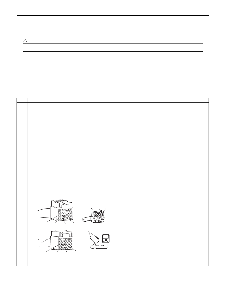
6) Using service wire (1), connect “E13-1” and “E13-2” 

terminal (for DTC B1074) or “E24-1” and “E24-2” 
terminal (for DTC B1078) of forward-sensor connector.

7) Measure resistance between “G47-9” and “G47-17” (for 

DTC B1074) or “G47-11” and “G47-19” (for DTC B1078) 
[A], or between “L33-9” and “L33-10” (for DTC B1074) or 
“L33-11” and “L33-12” (for DTC B1078) [B].

Special tool
(A):  09932–76010 

Is each measured resistance 1 

 or less?

Go to Step 2.

For DTC B1074: High 
resistance or open wire 
in “ORN” circuit or 
“PNK/BLK” circuit.
For DTC B1078: High 
resistance or open wire 
in “PNK” circuit or “PNK/
BLU” circuit.

“E13-1”, “E24-1”

“E13-2”, “E24-2”

1

[A]

[B]

“L33-12”

“L33-9” “L33-10” “L33-11”

“G47-9” “G47-17” “G47-19” “G47-11”

(A)

I5JB0A820051-01

Air Bag System:  8B-69

NOTE
Upon completion of inspection and repair work, perform the following items.
• Reconnect all air bag system components and ensure all components are properly mounted.
• Clear DTCs referring to “DTC Clearance”, if any
.
• Repeat “Air Bag Diagnostic System Check” 
to confirm that the trouble has been corrected.


2

1) Disconnect service wire from “E13” or “E24” connector.
2) Measure voltage between “G47-9” and body ground, 

“G47-17” and body ground (for DTC B1074) or “G47-11” 
and body ground, “G47-19” and body ground (for DTC 
B1078) [A], or between “L33-9” and body ground, “L33-
10” and body ground (for DTC B1074) or “L33-11” and 
body ground, “L33-12” and body ground (for DTC 
B1078) [B].

Special tool
(A):  09932–76010 

With ignition switch ON, is each measured value 1 V or less?

Go to Step 3.

For DTC B1074: “ORN” 
circuit or “PNK/BLK” 
circuit shorted to power 
circuit.
For DTC B1078: “PNK” 
circuit or “PNK/BLU” 
circuit shorted to power 
circuit.

3

1) Check forward-sensor referring to “Forward-Sensor 

Inspection”.

Is it in good condition?

Substitute a known-
good SDM and recheck.

Replace forward-sensor 
referring to “Forward-
Sensor Removal and 
Installation”. If DTC 
still 
exists, substitute a 
known-good SDM and 
recheck.

Step

Action

Yes

No

(A)

[A]

[B]

“G47-11”

“G47-9” “G47-17”  “G47-19 ”

“L33-9”

“L33-10”

“L33-11” “L33-12”

I5JB0A820052-01

8B-70 Air Bag System: 

DTC B1085: Wrong Side-Sensor ID

S5JB0A8204042

DTC Will Set when
SDM receives wrong ID (Part No.) signal from side-sensor.

DTC Troubleshooting

1) Turn ignition switch OFF.
2) Replace driver or passenger side-sensor referring to “Side-Sensor Removal and Installation”.
3) Repeat “Air Bag Diagnostic System Check”.

NOTE
Upon completion of inspection and repair work, perform the following items.
• Reconnect all air bag system components and ensure all components are properly mounted.
• Clear DTCs referring to “DTC Clearance”,
 if any.
• Repeat “Air Bag Diagnostic System Check” 
to confirm that the trouble has been corrected.


DTC B1086 / B1096: Left / Right Side-Sensor Performance Problem

S5JB0A8204038

DTC Will Set when
SDM receives internal fault signal from side-sensor.

DTC Troubleshooting

1) Turn ignition switch OFF.
2) Replace left or right side-sensor referring to “Side-Sensor Removal and Installation”.
3) Repeat “Air Bag Diagnostic System Check”.

NOTE
Upon completion of inspection and repair work, perform the following items.
• Reconnect all air bag system components and ensure all components are properly mounted.
• Clear DTCs referring to “DTC Clearance”,
 if any.
• Repeat “Air Bag Diagnostic System Check” 
to confirm that the trouble has been corrected.


DTC B1087 / B1097: Left / Right Side-Sensor Communication Error

S5JB0A8204039

Wiring Diagram

CAUTION

!


Be sure to observe instructions under CAUTION in “Air Bag Diagnostic System Check Flow”.


BLK

G46-16 GND

“G46”

1

2

4

3

RED

BLK/YEL

“G01”

G46-11

IG

L33-15

L33-16

SR+

SR-

L33-14

L33-13

SL+

SL-

“L33”

WHT/RED

LT GRN/BLK

WHT/GRN

LT GRN

“L11”

“L35”

8

5

6

7

I5JB0A820053-02

1. From main fuse

4. Junction block assembly

7. Right side-sensor

2. Ignition switch

5. SDM

8. Ground for air bag system

3. “A/B” fuse

6. Left side-sensor

Air Bag System:  8B-71

DTC Will Set when
Side-sensor abnormal signal is detected by SDM.

Flow Test Description
Step 1: Check for open circuit in forward sensor circuit.
Step 2: Check for short circuit between forward sensor circuit and ground.
Step 3: Check for short circuit between forward sensor circuit and power supply circuit.
Step 4: Check if malfunction is in forward sensor.

DTC Troubleshooting

Step

Action

Yes

No

1

1) Disconnect side-sensor connector “L35” or “L11”.
2)  Disconnect SDM connector “L33”.
3) Check proper connection to SDM connector at terminals 

“L33-13” and “L33-14” or “L33-15” and “L33-16”.

4) Check proper connection to side-sensor connector at 

terminals “L35-1” and “L35-2” or “L11-1” and “L11-2”.

5) Using service wire (1), connect “L35-1” and “L35-2” 

terminal (for DTC B1087) or “L11-1” and “L11-2” terminal 
(for DTC B1097) of side-sensor connector.

6) Measure resistance between terminals “L33-13” and 

“L33-14” (for DTC B1087) or terminals “L33-15” and 
“L33-16” (for DTC B1097) of SDM connector.

Special tool
(A):  09932–76010 

Is each measured resistance 1 

 or less?

Go to Step 2

For DTC B1087: High 
resistance or open wire 
in “WHT/RED” circuit or 
“LT GRN/BLK” circuit.
For DTC B1097: High 
resistance or open wire 
in “WHT/GRN” circuit or 
“LT GRN” circuit.

2

Measure resistance between “L33-13” terminal and body 
ground, and “L33-14” terminal and body ground (for DTC 
B1087) or between “L33-15” terminal and body ground, and 
“L33-16” terminal and body ground (for DTC B1097).

Special tool
(A):  09932–76010 

Is each measured resistance infinity?

Go to Step 3.

For DTC B1087: “WHT/
RED” circuit or “LT 
GRN/BLK” circuit 
shorted to ground.
For DTC B1087: “WHT/
GRN” circuit or “LT 
GRN” circuit shorted to 
ground.

“L35-1”, “E11-1”

“L35-2”, “L11-2”

1

(A)

“L33-13” “L33-14” “L33-15” “L33-16”

I5JB0A820054-01

“L33-13” “L33-14” “L33-15” “L33-16”

(A)

I5JB0A820055-01


Content   ..  316  317  318  319   ..