Suzuki Grand Vitara JB416 / JB420. Manual - part 276


  Index      Suzuki     Suzuki Grand Vitara JB416 / JB420- service repair manual


Search            


Content   ..  274  275  276  277   ..


Suzuki Grand Vitara JB416 / JB420. Manual - part 276


7A-10 Heater and Ventilation: 

Blower Motor Controller Removal and 
Installation

S5JB0A7106005

Removal

1) Disconnect negative (–) cable at battery.
2) Disable air bag system referring to “Disabling Air 

Bag System in Section 8B”.

3) Remove glove box.
4) Remove passenger lower member.
5) Disconnect blower motor controller coupler (3).
6) Remove blower motor controller (1) by loosening its 

fastening screws (2).

Installation

1) Reverse removal procedure.
2) Enable air bag system referring to “Enabling Air Bag 

System in Section 8B”.

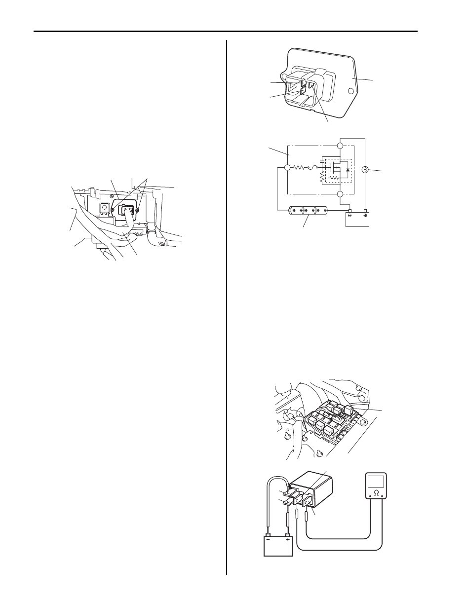
Blower Motor Controller Inspection

S5JB0A7106006

Check controller for operation as follows.
• Using service wire, connect battery positive terminal 

to “1” terminal (1) of blower motor controller (6) and 
battery negative terminal to “2” terminal (2) of blower 
motor controller.

• Using bulb (3.4 W) (4) and service wire, connect 

battery positive terminal to “3” terminal (3) of blower 
motor controller as shown figure.

• Arrange 3 new 1.5 V batteries (5) in series (check that 

total voltage is 4.5 – 5.0 V) and connect its positive 
terminal to “3” terminal of blower motor controller and 
negative terminal to “2” terminal of blower motor 
controller. Then, check that bulb lights. If bulb does 
not light under the above conditions, replace blower 
motor controller.

Blower Motor Relay Inspection

S5JB0A7106008

1) Disconnect negative (–) cable at battery.
2) Remove blower motor relay (1) from vehicle.
3) Check that there is no continuity between terminal 

“c” and “d”. If there is continuity, replace relay.

4) Connect battery positive (+) terminal to terminal “b” 

of relay.
Connect battery negative (–) terminal to terminal “a” 
of relay.
Check continuity between terminal “c” and “d”.
If there is no continuity when relay is connected to 
the battery, replace relay.

3

1

2

I5JB0A710009-01

6

6

1

1

2

2

3

3

4

5

I5JB0A710010-01

1

“d”

“a”

“b”

“c”

I5JB0A710011-01

Heater and Ventilation:  7A-11

Heater Core Removal and Installation

S5JB0A7106010

Removal

1) Remove instrument panel referring to “Instrument 

Panel Removal and Installation in Section 9C”.

2) Remove HVAC unit. Refer to “HVAC Unit Removal 

and Installation in Section 7B”.

3) Remove heater core pipe clamp and then, pull out 

heater core (1) from HVAC unit.

Installation

1) Install heater core by reversing removal procedure, 

noting the following items.
• When installing heater core, be careful not to 

damage fins of heater core.

• When installing each part, be careful not to catch 

any wiring harness.

2) Fill engine coolant to radiator.
3) Enable air bag system referring to “Enabling Air Bag 

System in Section 8B”.

HVAC Control Module Removal and Installation

S5JB0A7106011

Removal

1) Disconnect negative (–) cable at battery.
2) Remove center garnish with audio unit (if equipped) 

and HVAC control module referring to “Audio Unit 
Removal and Installation in Section 9C”.

3) Remove HVAC control module mounting screws and 

then, remove HVAC control module (2) from center 
garnish (1).

Installation
Reverse removal procedure.

HVAC Control Module and Its Circuits 
Inspection (for Vehicle without A/C)

S5JB0A7106012

HVAC control module and its circuits inspection is the 
same as vehicle equipped with A/C system.
Refer to “HVAC Control Module and Its Circuits 
Inspection in Section 7B”
.

Air Flow Control Actuator Removal and 
Installation

S5JB0A7106013

Removal

1) Disconnect negative (–) cable at battery.
2) Remove steering column hole cover from instrument 

panel.

3) Disconnect air flow control actuator connector (2).
4) Remove screws and then, remove air flow control 

actuator (1) from HVAC unit.

Installation
Reverse removal procedure.

Air Flow Control Actuator Inspection

S5JB0A7106014

1) Remove air flow control actuator (1) referring to “Air 

Flow Control Actuator Removal and Installation”. 

2) Check resistance between “d” and “e” terminals.

Air flow control actuator resistance
DEF position: Approx. 700 

FOOT / BENT position: Approx. 1.7 k

FOOT position: Approx. 2.4 k

BI-LEVEL position: Approx. 3.9 k

VENT position: Approx. 5.1 k

3) Connect battery positive (+) terminal to terminal “a” 

and battery negative (–) terminal to terminal “b”. 
Check if position of air flow control actuator changes 
VENT position to DEF position.

1

I5JB0A710012-02

1

2

I5JB0A710013-01

1

2

I5JB0A710014-02

7A-12 Heater and Ventilation: 

4) Connect battery positive (+) terminal to terminal “b” 

and battery positive (–) terminal to terminal “a”. 
Check if position of air flow control actuator changes 
DEF position to VENT position.
If malfunction is found, replace air flow control 
actuator with new one.

Temperature Control Actuator Removal and 
Installation

S5JB0A7106015

Removal

1) Disconnect negative (–) cable at battery.
2) Remove steering column hole cover from instrument 

panel.

3) Disconnect temperature control actuator connector 

(2).

4) Remove screws (3) and then, remove temperature 

control actuator (1) from HVAC unit.

Installation
Reverse removal procedure.

Temperature Control Actuator Inspection

S5JB0A7106016

1) Remove temperature control actuator (1). Refer to 

“Temperature Control Actuator Removal and 
Installation”. 

2) Check resistance between “d” and “e” terminals.

Temperature control actuator resistance
Max cold position: Approx. 480 

Max hot position: Approx. 3.9 k

3) Connect battery positive (+) terminal to terminal “b” 

and battery negative (–) terminal to terminal “a”. 
Check if position of actuator lever changes COLD 
position to HOT position.

4) Connect battery positive (+) terminal to terminal “a” 

and battery positive (–) terminal to terminal “b”. 
Check if position of actuator lever changes HOT 
position to COLD position.
If malfunction is found, replace temperature control 
actuator with new one.

A: VENT position

D: DEF / FOOT position (Approx. 50

°)

B: BI-LEVEL position (Approx. 22

°)

E: DEF position

C: FOOT position (Approx. 40

°)

F: Approx. 82

°

“a”

“b”

“c”

“d”

“e”

E

D

C

B

F

A

1

“a” “b” “c”

“d” “e”

I5JB0A710015-03

2

1

3

I5JB0A710016-01

A: Max cold position
B: Max hot position

C: Approx. 72

°

“a”

“b”

“c”

“d”

“e”

A

C

B

1

“a” “b” “c”

“d” “e”

I5JB0A710017-03

Heater and Ventilation:  7A-13

Air Intake Control Actuator Removal and 
Installation

S5JB0A7106017

Removal

1) Disconnect negative (–) cable at battery.
2) Remove glove box.
3) Disconnect air intake control actuator connector (2).
4) Remove screws and then, remove air intake control 

actuator (1) from HVAC unit.

Installation
Reverse removal procedure.

Air Intake Control Actuator Inspection

S5JB0A7106018

1) Remove air intake control actuator (1). Refer to “Air 

Intake Control Actuator Removal and Installation”. 

2) Check resistance between “d” and “e” terminals of 

actuator.

Air intake control actuator resistance
LH steering vehicle
REC position: Approx. 4.5 k

FRE position: Approx. 1.2 k

RH steering vehicle
REC position: Approx. 1.2 k

FRE position: Approx. 4.5 k

3) Connect battery positive (+) terminal to terminal “a” 

and battery negative (–) terminal to terminal “b”. 
Check if position of actuator lever is REC position.

4) Connect battery positive (+) terminal to terminal “b” 

and battery negative (–) terminal to terminal “a”. 
Check if position of actuator lever is FRESH position.

Actuator Linkage Inspection

S5JB0A7106019

• Check if each actuator linkage operates smoothly.
• Check actuator rod for bend.
• Check each actuator linkage for breakage.
• Make sure if there is not any obstruction in operating 

range of actuator linkage.

If any malfunction is found, repair or replace faulty 
part(s).

1

2

I5JB0A710018-01

[A]: LH steering vehicle
[B]: RH steering vehicle

C: REC position
D: FRESH position

E: Approx. 60

°

“a”

“b”

“c”

“d”

“e”

“a” “b” “c” “d”

“e”

1

C

E

D

C

E

[A]

[B]

D

1

I5JB0A710019-03


Content   ..  274  275  276  277   ..