Suzuki Grand Vitara JB416 / JB420. Manual - part 264


  Index      Suzuki     Suzuki Grand Vitara JB416 / JB420- service repair manual


Search            


Content   ..  262  263  264  265   ..


Suzuki Grand Vitara JB416 / JB420. Manual - part 264


6B-4 Steering Wheel and Column: 

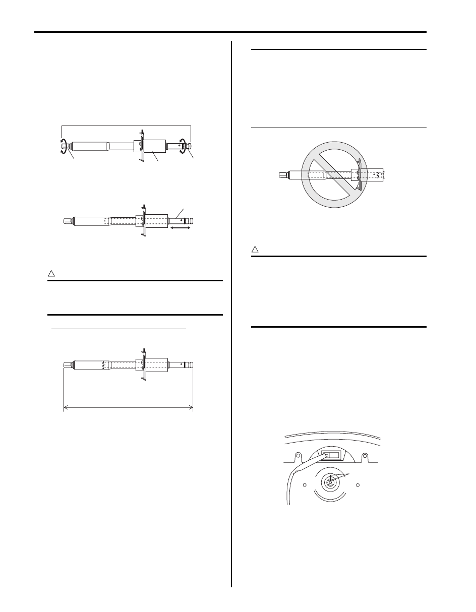
• Check steering upper shaft assembly for following 

conditions.
– Steering upper shaft assembly (1) is not bent or 

damaged.

– Lower seal (2) is not damaged.
– Upper joint (3) turns with light hand force and lower 

joint (4) turns at the same time.

– Shaft (1) expands and contracts easily with light 

force.

– When shaft is made to contract with light force until 

it stops, its length “a” is longer than specified value.

CAUTION

!


Do not apply excessive force to shaft when 
making it contract. Its internal plug may be 
damaged.


Steering upper shaft assembly length
“a”: 363.0 mm (14.29 in.)

NOTE
If shaft has come off in sleeve due to an 
accident or some other reason as shown in 
figure, its internal plug has come off or been 
damaged. The same applies when length of 
steering upper shaft assembly is short.
When anything faulty is noted in above 
check, replace steering upper shaft assembly 
with a new one.


Steering Wheel Removal and Installation

S5JB0A6206002

CAUTION

!


Removal of the steering wheel allows the 
contact coil cable assembly to turn freely but 
do not turn the contact coil cable assembly 
more than allowable number of turns (about 
two and a half turns from the center position 
clockwise or counterclockwise respectively), 
or coil will break.


Removal

1) Remove driver air bag (inflator) module from 

steering wheel referring to “Driver Air Bag (Inflator) 
Module Removal and Installation in Section 8B”
.

2) Disconnect horn connector and audio control switch 

connector, if equipped.

3) Remove steering shaft nut.
4) Make alignment marks (1) on steering wheel and 

shaft for a guide during reinstallation.

4

2

1

3

I5JB0A620004-01

1

I5JB0A620005-01

“a”

I5JB0A620006-02

I5JB0A620007-03

1

I5JB0A620008-01

Steering Wheel and Column:  6B-5

5) Remove steering wheel (1) with special tool.

CAUTION

!


Do not hammer the end of the shaft. 
Hammering it will loosen the plastic shear 
pins which maintain the column length and 
impair the collapsible design of the column.


Special tool
(A):  09944–36011

Installation

1) Check that vehicle’s front tires are at straight-ahead 

position and contact coil cable assembly is centered. 
Refer to “Centering Contact Coil Cable Assembly”.

CAUTION

!


These two conditions are prerequisite for 
installation of steering wheel. If steering 
wheel has been installed without these 
conditions, contact coil cable assembly will 
break when steering wheel is turned.


2) Install steering wheel (1) to steering shaft with 2 lugs 

(2) on contact coil cable assembly fitted in two 
grooves (3) in the back of steering wheel and also 
aligning marks (4) on steering wheel and steering 
shaft.

3) Tighten steering shaft nut to specified torque.

Tightening torque
Steering shaft nut:  33 N·m (3.3 kgf-m, 24.0 lb-ft)

4) Connect horn connector and audio control switch 

connector, if necessary.

5) Install driver air bag (inflator) module to steering 

wheel. Refer to “Driver Air Bag (Inflator) Module 
Removal and Installation in Section 8B”.

Contact Coil Cable Assembly Removal and 
Installation

S5JB0A6206013

CAUTION

!


Do not turn contact coil cable assembly more 
than allowable number of turns (about two 
and a half turns from the center position 
clockwise or counterclockwise respectively), 
or coil will break.


Removal

1) Remove steering wheel from steering column. Refer 

to “Steering Wheel Removal and Installation”.

2) Remove steering column hole cover (1).

(A)

1

I5JB0A620009-01

I5JB0A620010-01

1

I5JB0A620011-01

6B-6 Steering Wheel and Column: 

3) Remove steering column cover screws (1) (3 

pieces).

4) Separate upper cover (2) and lower cover (3), then 

remove them.

5) Disconnect all connectors for contact coil cable 

assembly.

6) Remove contact coil cable assembly (1) from 

steering column.

Installation

1) Check to make sure that vehicle’s front tires are set 

at straight-ahead position and then ignition switch is 
at “LOCK” position.

2) Install contact coil cable assembly to steering 

column.

NOTE
New contact coil cable assembly is supplied 
with contact coil cable assembly set and held 
at its center position with a lock pin (1). 
Remove this lock pin after installing contact 
coil cable assembly to steering column.


3) Connect all connectors that have been removed in 

“Removal”.

4) Install steering column upper cover (2) and lower 

cover (3), and then tighten steering column cover 
screws (1).

CAUTION

!


When installing lower cover (3) and upper 
cover (2), be careful so that each lead wire is 
not caught between covers.


5) Install steering column hole cover (1).

6) Install steering wheel to steering column. Refer to 

“Steering Wheel Removal and Installation”.

1

3

1

2

I5JB0A620012-01

1

I5JB0A620013-01

I5JB0A620014-01

*: Standard screw

**: Tapping screw

1*

3

1**

2

I5JB0A620015-01

1

I5JB0A620011-01

Steering Wheel and Column:  6B-7

Contact Coil Cable Assembly Inspection

S5JB0A6206014

CAUTION

!


Do not turn contact coil cable assembly more 
than allowable number of turns (about two 
and a half turns from the center position 
clockwise or counterclockwise respectively), 
or coil will break.


Check contact coil cable assembly (1) wire harness for 
any signs of scorching, melting or other damage. 
If it is damaged, replace.

Centering Contact Coil Cable Assembly

S5JB0A6206003

CAUTION

!


Removal of the steering wheel allows the 
contact coil cable assembly to turn freely but 
do not turn the contact coil cable assembly 
more than allowable number of turns (about 
two and a half turns from the center position 
clockwise or counterclockwise respectively), 
or coil will break.


1) Check that vehicle’s wheels (front tires) are set at 

straight-ahead position.

2) Check that ignition switch is at LOCK position.
3) Turn contact coil cable assembly (2) 

counterclockwise slowly with a light force till contact 
coil cable assembly will not turn any further.

NOTE
Contact coil cable assembly can turn about 5 
turns at maximum, that is, if it is at the center 
position, can turn about two and a half turns 
both clockwise and counterclockwise.


4) From the position where contact coil cable assembly 

(2) became unable to turn any further (it stopped), 
turn it back clockwise about two and a half rotations 
and align center mark with alignment mark (1).

Steering Column Assembly Removal and 
Installation

S5JB0A6206006

CAUTION

!


Once the steering column assembly is 
removed from the vehicle, the column is 
extremely susceptible to damage.
Dropping the column assembly on its end 
could collapse the steering shaft or loosen 
the plastic shear pins which maintain column 
length leaning on the column assembly could 
cause it to bend or deform.
Any of the above damage could impair the 
column’s collapsible design.
When loosening steering column mounting 
bolts and nuts, make sure that steering 
column assembly and steering upper shaft 
assembly have been separated. Loosening 
them with steering column assembly and 
steering upper shaft assembly assembled 
could cause damage to upper joint and 
mounting bracket in steering upper shaft 
assembly.


1

I5JB0A620016-01

[A]: Turn slowly till coil stops
[B]: Turn contact coil cable assembly back about 2 and a half turns

1

2

2

[A]

[B]

I5JB0A620017-03


Content   ..  262  263  264  265   ..