Suzuki Grand Vitara JB416 / JB420. Manual - part 260


  Index      Suzuki     Suzuki Grand Vitara JB416 / JB420- service repair manual


Search            


Content   ..  258  259  260  261   ..


Suzuki Grand Vitara JB416 / JB420. Manual - part 260


5C-4 Clutch: 

Repair Instructions

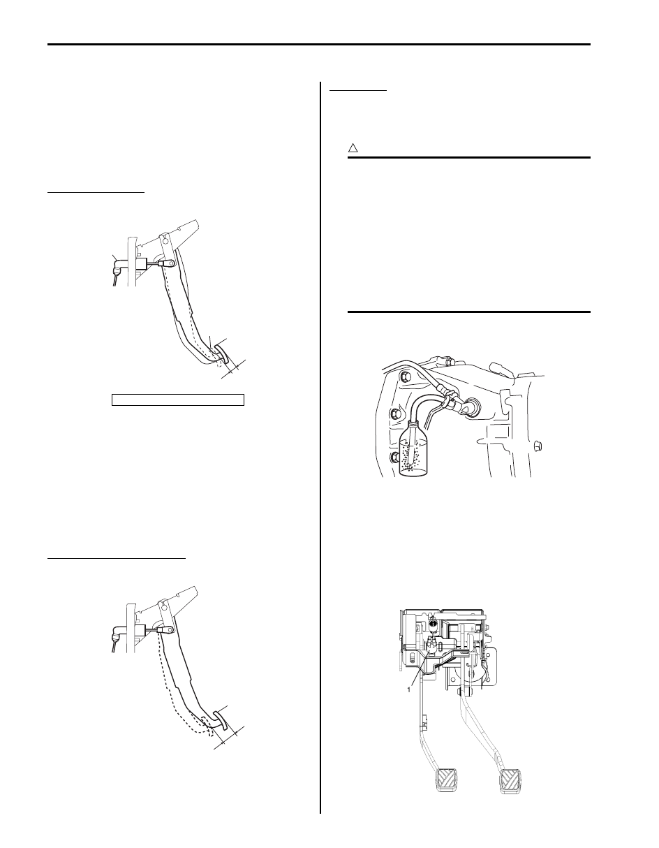
Clutch Pedal Height Inspection

S5JB0A5306014

Measure clutch pedal height “a” from brake pedal (2). If 
pedal height is excessive low or high, check installation 
position of clutch position switch, clutch fluid leakage, 
bending of clutch pedal arm and bending of push rod of 
clutch master cylinder (3). If any abnormality is found, 
adjust or replace it with a new one.

Clutch pedal height
“a”: Approx. 20 mm (0.79 in.)

Clutch Pedal Free Travel Check

S5JB0A5306015

Depress clutch pedal (1), stop the moment clutch 
resistance is felt and measure distance (clutch pedal 
free travel). Free travel should be within the following 
specification. If free travel is out of specification, check 
installation position of clutch pedal position switch, clutch 
fluid leakage, bending of clutch pedal arm and bending 
of push rod of clutch master cylinder. If any abnormality 
is found, adjust or replace it with a new one.

Clutch pedal free travel  “a”
: 0 – 10 mm (0 – 0.4 in.)

Clutch Fluid Inspection

S5JB0A5306016

Refer to “Brake Fluid Level Check in Section 4A”.

Clutch fluid
: Refer to reservoir cap.

Air Bleeding of Clutch System

S5JB0A5306017

CAUTION

!


• Brake fluid is extremely damaging to paint. 

If fluid should accidentally touch painted 
surface, immediately wipe fluid from paint 
and clean painted surface.

• When operating the pedal stroke for air 

bleeding of clutch system, after releasing 
the clutch pedal, be sure to wait 1 second 
or more before depressing it again. 
Otherwise, the oil seal of operating 
cylinder will be damaged, resulting in oil 
leakage.


Bleed air from clutch system. Refer to “Air Bleeding of 
Brake System in Section 4A” for
 air bleeding procedure.

Clutch Pedal Position (CPP) Switch Removal 
and Installation

S5JB0A5306001

Removal

1) Disconnect connector of CPP switch (1) with ignition 

switch OFF.

2) Remove CPP switch (1) from pedal bracket.

1. Clutch pedal

3

2

1

“a”

I5JB0A530003-01

1

“a”

I5JB0A530004-01

I5JB0A530015-03

I5JB0A530005-02

Clutch: 5C-5

Installation

1) Instal CPP switch to pedal bracket.
2) Adjust switch position referring to “Clutch Pedal 

Position (CPP) Switch Inspection and Adjustment”.

3) Connect connector to CPP switch securely.

Clutch Pedal Position (CPP) Switch Inspection 
and Adjustment

S5JB0A5306002

Inspection
Check for resistance between terminals under each 
condition below. If check result is not satisfactory, 
replace.

CPP switch resistance
When switch shaft is pushed (1): Continuity
When switch shaft is free (2): No continuity

Adjustment
With clutch pedal (1) released, adjust switch (2) position 
so that clearance between end of thread and clutch 
pedal arm is within specification.

Clearance between end of thread and clutch pedal 
arm
“a”: 0.5 – 1.5 mm (0.02 – 0.06 in.)

Clutch Fluid Pipe and Hose Removal and 
Installation

S5JB0A5306003

CAUTION

!


Do not allow fluid to get on painted surface. It 
may cause painted surface damage.


Removal

1) Remove dust and dirt from each joint of hose and 

pipe to be disconnected and clean around reservoir 
cap of brake master cylinder.

2) Take out fluid with syringe or such.
3) Remove clamp (1) of clutch master cylinder (2) and 

disconnect fluid pipe (3).

4) Disconnect fluid pipe (1) from hose (2).

NOTE
To disconnect pipe (1) from hose (2), 
separate them by using flare nut wrench (4) 
and spanner (3) so as not to kink them.


5) Pull clamp (1) of fluid pipe joint (2) and disconnect 

fluid hose (3).

I5JB0A530006-01

1

1

2

3

“a”

I5JB0A530007-02

1

2

3

I5JB0A530008-01

1

2

3

4

I5JB0A530009-03

1

3

2

I5JB0A530010-02

5C-6 Clutch: 

Installation
Reverse removal sequence noting the following points.
• Tighten flare nut (3) and hose bracket nut (4) to 

specified torque.

Tightening torque
Clutch fluid pipe flare nut (a):  16 N·m (1.6 kgf-m, 
11.5 lb-ft)
Clutch fluid hose bracket nut (b):  10 N·m (1.0 kgf-
m, 7.5 lb-ft)

• Do not allow pipe (1) and hose (2) to contact hard 

against vehicle or other parts.

• Install each clamp securely.
• After installation, check clutch pedal free travel and 

bleed air from system.

• Check fluid leakage.
• Add fluid close to MAX level of reservoir.

Clutch Fluid Pipe and Hose Inspection

S5JB0A5306004

Check pipe (1) and hose (2) for dent, kink, crack, dirt and 
dust. Replace if check result is not satisfactory.

Clutch Master Cylinder Removal and 
Installation

S5JB0A5306005

CAUTION

!


• Do not allow fluid to get on painted 

surfaces. It may cause painted surface 
damage.

• Do not disassemble clutch master 

cylinder.


Removal

1) Clean around reservoir cap of brake master cylinder 

and take out fluid with syringe or such.

2) Detach main fuse box.
3) Disconnect fluid pipe (2) and reservoir hose (4) from 

master cylinder assembly (1).

4) Remove clip (6) and push rod clevis pin (5).
5) Remove master cylinder attaching nuts (3).
6) Remove master cylinder assembly (1) and gasket.

1

3, (a)

4, (b)

2

I5JB0A530011-03

2

1

2

I5JB0A530012-03

1

2

3

4

3

6

5

I5JB0A530013-01

Clutch: 5C-7

Installation
Reverse removal procedure for installation noting the 
following.
• Apply grease to push rod clevis pin (1).

“A”:  Grease 99000–25100 (SUZUKI Silicone Grease)

• Tighten master cylinder attaching nuts (2) to specified 

torque.

Tightening torque
Clutch master cylinder attaching nut (a):  23 N·m (
2.3 kgf-m, 17.0 lb-ft)

• Fill reservoir with specified brake fluid and check fluid 

leakage.

• After installation, bleed air from clutch system and 

check clutch pedal free travel. Refer to “Air Bleeding 
of Brake System in Section 4A” 
for air bleeding 
procedure.

Clutch Master Cylinder Inspection

S5JB0A5306008

• Check master cylinder (1) for damage and fluid 

leakage, boot for damage and deterioration, gasket 
for damage and deterioration.

• Check for push rod clevis distance “a” and clevis pin 

hole diameter “b” as shown.

If any malfunction is found, replace master cylinder.

Push rod clevis distance “a”:
106.1 – 107.1 mm (4.18 – 4.22 in.)

Clevis pin hole diameter “b”:
10.05 – 10.15 mm (0.396 – 0.399 in.)

Clutch Operating Cylinder Assembly Removal 
and Installation

S5JB0A5306009

CAUTION

!


• Do not allow fluid to get on painted 

surfaces. It may cause painted surface 
damage.

• Do not disassemble clutch operating 

cylinder assembly.


Removal

1) Clean around reservoir cap of brake master cylinder 

and take out fluid with syringe or such.

2) Dismount transmission assembly referring to 

“Manual Transmission Assembly Dismounting and 
Remounting in Section 5B”
.

3) Loosen clutch fluid pipe flare nut (1) of clutch 

operating cylinder assembly (2).

4) Remove clutch pipe joint sleeve (3) from 

transmission front case and then remove clutch fluid 
pipe (4).

5) Remove clutch operating cylinder assembly from 

transmission front case.

1, “A”

2, (a)

2, (a)

I5JB0A530014-01

I5JB0A530015-03

“b”

“a”

1

I5JB0A530016-01

3

1

2

4

I5JB0A530017-01


Content   ..  258  259  260  261   ..