Suzuki Grand Vitara JB416 / JB420. Manual - part 254


  Index      Suzuki     Suzuki Grand Vitara JB416 / JB420- service repair manual


Search            


Content   ..  252  253  254  255   ..


Suzuki Grand Vitara JB416 / JB420. Manual - part 254


5B-12 Manual Transmission/Transaxle: 

Installation

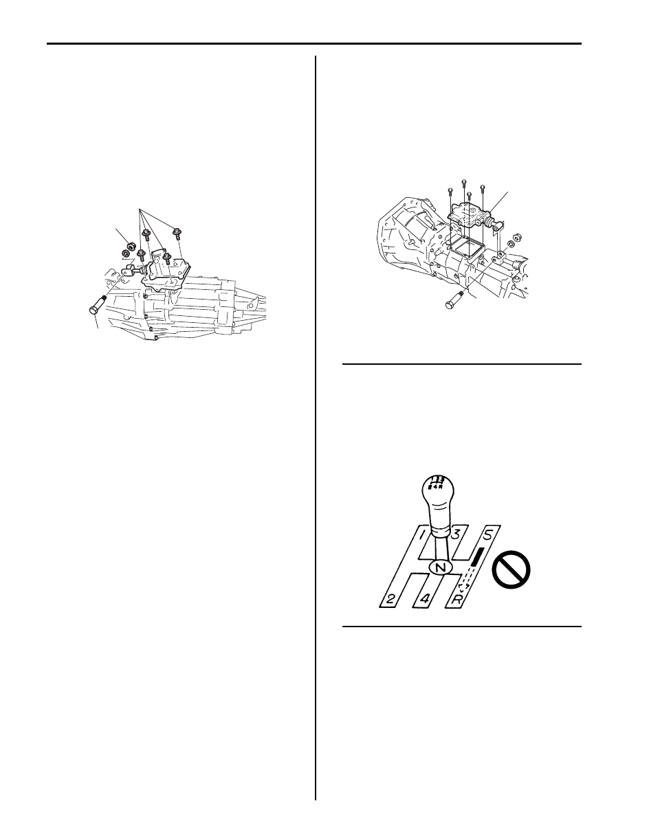
1) Install gear shift control lever rear case assembly 

with its plate to transfer case referring to figure for 
proper installing direction of control shaft joint bolt 
(2). Tighten plate bolts (1) and control shaft joint nut 
(3) to specified torque.

Tightening torque
Plate bolt (a):  23 N·m (2.3 kgf-m, 17.0 lb-ft)
Control shaft joint nut (b):  18 N·m (1.8 kgf-m, 
13.0 lb-ft)

2) Remount transmission assembly to vehicle referring 

to “Manual Transmission Assembly Dismounting and 
Remounting”

Gear Shift Control Lever Rear Case Assembly 
Disassembly and Reassembly

S5JB0A5206029

Disassembly and reassembly component parts referring 
to “Gear Shift Control Lever Rear Case Assembly 
Components”.

Gear Shift Control Lever Rear Case Assembly 
Inspection

S5JB0A5206030

• Check that gear shift control shaft moves smoothly 

without abnormal noise. If abnormality is found, 
replace defective part.

• Check bush and boot for damage and deterioration. If 

abnormality is found, replace defective part.

Gear Shift Lever Front Case Assembly Removal 
and Installation

S5JB0A5206031

Removal

1) Dismount transmission assembly referring to 

“Manual Transmission Assembly Dismounting and 
Remounting”

2) Remove gear shift lever front case assembly (1) 

from transmission rear case.

Installation

NOTE

• Install gear shift lever front case to 

transmission rear case without using 
sealant for functional check.

• Install shift control lever and check to 

make sure that it shifts smoothly 
according to shift pattern as shown in the 
figure.


1, (a)

2

3, (b)

I5JB0A520008-03

1

I5JB0A520009-03

I5JB0A520010-01

Manual Transmission/Transaxle:  5B-13

1) Clean mating surface of both rear case and gear 

shift lever front case (2), and uniformly apply sealant 
to lever case as shown in figure by such amount that 
its section is 1.2 mm (0.047 in.) in diameter, and then 
mate it with gear shift lever front case.

“A”:  Sealant 99000–31260 (SUZUKI Bond 
No.1217G)

2) Install lever case to rear case and then tighten new 

lever case bolts (1) to specified torque.

Tightening torque
Gear shift lever front case bolt (a):  23 N·m (2.3 
kgf-m, 17.0 lb-ft)

3) Connect gear shift shaft (3) of lever case assembly 

to gear shift control shaft (4) of gear shift control 
lever rear case assembly referring to figure for 
proper installing direction of control shaft joint bolt 
(5). Tighten control shaft joint nut (6) to specified 
torque.

Tightening torque
Control shaft joint nut (b):  18 N·m (1.8 kgf-m, 
13.0 lb-ft)

4) Remount transmission assembly referring to 

“Manual Transmission Assembly Dismounting and 
Remounting”

Gear Shift Lever Front Case Assembly 
Disassembly and Reassembly

S5JB0A5206032

Disassembly

1) Remove gear shift case plug.
2) Drive out gear shift arm pin using special tool, and 

then disassemble components parts.

CAUTION

!


Be careful to disconnect gear shift shaft from 
gear shift lever front case so that gear shift 
locating ball and gear shift locating spring 
may be jumped out.


Special tool
(A):  09925–78210

Reassembly

1) Install new gear shift shaft oil seal (1) to gear shift 

lever front case using special tool.

Special tool
(A):  09923–46020

1, (a)

3

5

4

6, (b)

2

“A”

2

I5JB0A520011-04

(A)

I5JB0A520012-01

1

(A)

I5JB0A520013-01

5B-14 Manual Transmission/Transaxle: 

2) Assemble components parts referring to “Gear Shift 

Lever Front Case Assembly Components”.

3) Set new gear shift arm inner pin (1) and outer pin (2) 

facing each gap (“a”, “b”) as shown in figure.
Drive gear shift arm pins by using special tool, till the 
length “c” becomes the specified. (The length “c” is 
the length of the pin protrusion from gear shift shaft 
(4) and select arm (3)).

Special tool
(A):  09925–78210

Gear shift arm pin protrusion “c”: 0.5–1.5 mm 
(0.020–0.059 in.)

Gear Shift Lever Front Case Assembly 
Inspection

S5JB0A5206033

• Check that gear shift shaft moves smoothly without 

abnormal noise. If abnormality is found, replace 
defective part.

• Check bushes and boot for damage and deterioration. 

If abnormality is found, replace defective part.

Engine Rear Mounting Replacement

S5JB0A5206010

When replacement of mounting parts are necessary, 
torque bolts as specified below.

Tightening torque
Engine rear mounting No.1 bolt (a):  55 N·m (5.5 kgf-
m, 40.0 lb-ft)
Engine rear mounting member bolt (b):  55 N·m (5.5 
kgf-m, 40.0 lb-ft)
Engine rear mounting No.2 bolt (c):  55 N·m (5.5 kgf-
m, 40.0 lb-ft)

Manual Transmission Assembly Dismounting 
and Remounting

S5JB0A5206011

Dismounting

1) Disconnect negative (–) cable of battery.
2) Remove transmission shift control lever referring to 

“Transmission Shift Control Lever Removal and 
Installation”.

3) Detach engine harness clamps and ground wire 

harness from transmission front case.

4) Remove starting motor fastening bolts (2) and 

transmission fastening bolts (1).

5. Case side

“a”

“b”

1

2

(A)

“c”

1, 2

3

4

5

I5JB0A520014-01

1. Engine rear mounting member
2. Engine rear mounting

I5JB0A520015-01

1

1

1

2

I5JB0A520016-01

Manual Transmission/Transaxle:  5B-15

5) Disconnect clutch fluid joint from pipe of clutch 

operating cylinder assembly referring to “Clutch 
Operating Cylinder Assembly Removal and 
Installation in Section 5C”.

6) Hoist vehicle.
7) Drain oil from transmission and transfer.
8) Remove propeller shafts referring to “Propeller Shaft 

Removal and Installation in Section 3D”.

9) Remove exhaust No. 2 pipe.

10) Remove engine under cover.

11) Remove clutch housing lower plates (1).

12) Remove transmission fastening nut (2) and bolts (3).

13) Disconnect the following couplers and release their 

harness from clamps.
• Back up light switch
• Transfer shift actuator (for J20 engine model)
• 4L/N switch (for J20 engine model)
• Center differential lock switch (for J20 engine 

model)

14) Apply transmission jack (1) and remove engine rear 

mounting member (2) taking off its bolts.

15) After removing mounting member, move rearward 

transmission and transfer assemblies placed on jack 
and then lower them.

16) Separate gear shift control lever rear case assembly 

(2) and transfer assembly (3) from transmission 
assembly (1).

2

1

1

3

3

I5JB0A520028-01

2

1

I5JB0A520029-01

2

1

3

I5JB0A520030-03


Content   ..  252  253  254  255   ..