Suzuki Grand Vitara JB416 / JB420. Manual - part 228
5A-46 Automatic Transmission/Transaxle:
“POWER” Light Circuit Check – Light Does Not Come “ON” at Ignition Switch ON
S5JB0A5104065
Troubleshooting
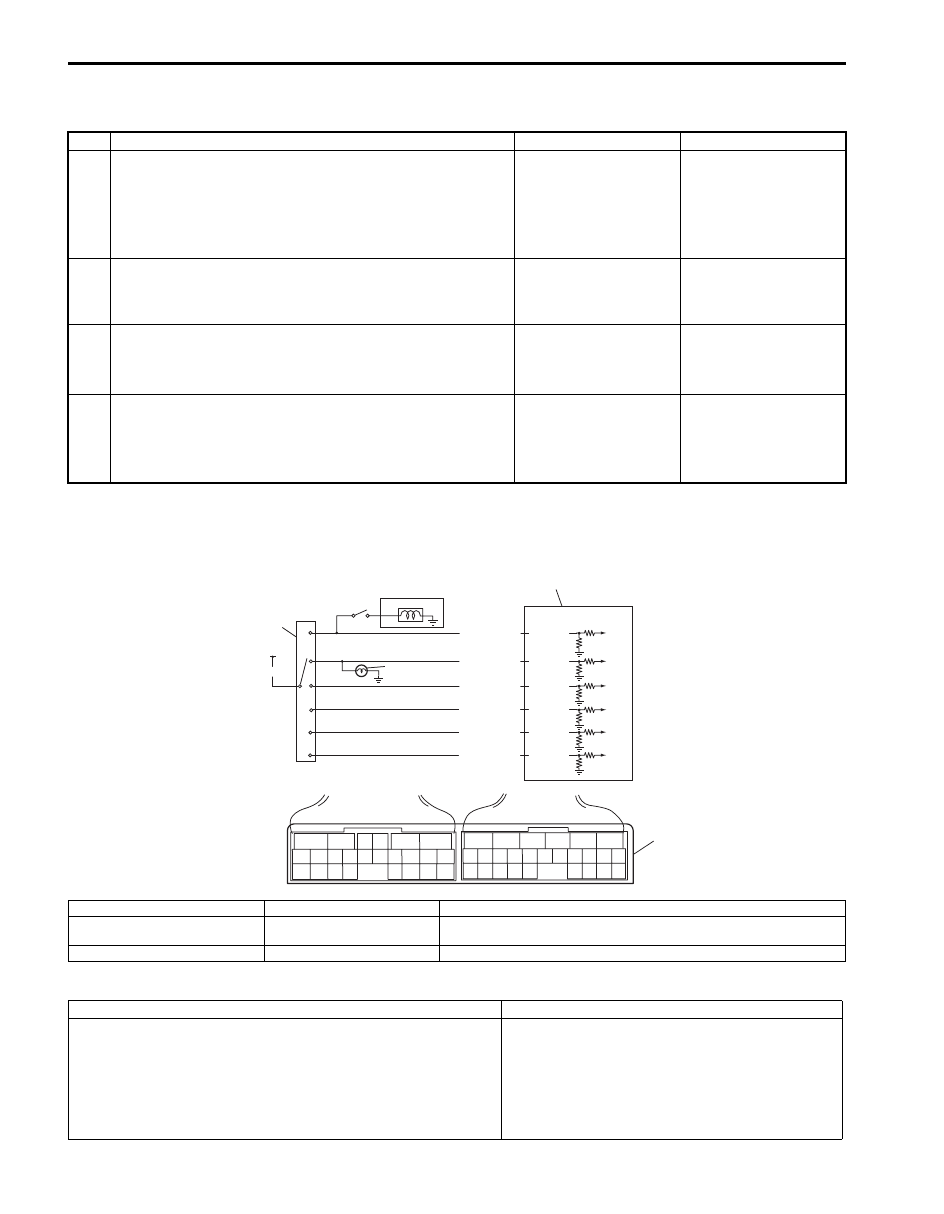
DTC P0705: Transmission Range Sensor Circuit Malfunction
S5JB0A5104026
Wiring Diagram
DTC Detecting Condition and Trouble Area
Step
Action
Yes
No
1
Combination Meter Power Supply Check
1) Turn ignition switch ON.
Does other indicator / warning lights in combination meter
comes ON?
Go to Step 2.
Repair combination
meter power supply
circuit referring to
“Combination Meter
Circuit Diagram in
Section 9C”.
2
1) TCM power and ground circuit check referring to “TCM
Power and Ground Circuit Check”.
Is it in good condition?
Go to Step 3.
Repair or replace.
3
DTC check
1) Check DTC referring to “DTC Check”.
Is there DTC P1774 or P1775?
Go to applicable DTC
diag. flow.
Go to Step 4.
4
Combination Meter Function Check
1) Turn ignition switch ON.
Does A/T selector position indicator show correct select
lever position?
Replace combination
meter.
Substitute a known-
good TCM and recheck.
2
6
1
4
P
R
N
D
2
L
5
3
BLK/RED
RED
YEL/GRN
PNK/BLU
PNK/GRN
GRN/ORN
GRN/WHT
E93-20
E93-1
E93-8
E93-7
E93-19
E93-18
6
5
16 15 14 13 12 11
4 3
24 23
21
22
10 9
8
7
2
1
19
20
18 17
E92
17 16
26 25
15 14
6
5
3
4
2
13 12
23 22
24
11 10 9
21 20 19
8 7
18
1
E93
7
I5JB0A510020-01
1. TCM
4. Brake light switch
7. Terminal arrangement of TCM connector (viewed from harness side)
2. Transmission range sensor
(switch)
5. Back-up light
3. From ignition switch
6. Shift lock solenoid
DTC Detecting Condition
Trouble Area
Multiple signals are inputted simultaneously for 2 seconds.
(1 driving cycle detection logic)
• Select cable maladjusted.
• Transmission range sensor (switch)
maladjusted.
• Transmission range sensor (switch) or its circuit
malfunction.
• TCM