Suzuki Grand Vitara JB416 / JB420. Manual - part 188


  Index      Suzuki     Suzuki Grand Vitara JB416 / JB420- service repair manual


Search            


Content   ..  186  187  188  189   ..


Suzuki Grand Vitara JB416 / JB420. Manual - part 188


3C-66 Transfer: Motor-Shift Type (Transfer with Shift Actuator)

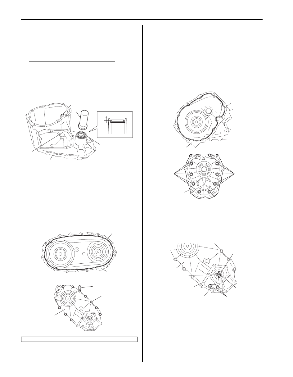
15) Install oil pipe (1) and knock pin (2) into center case 

(3).

16) Install new front oil seal No.1 (4) into center case 

using special tool as shown in figure, and then apply 
grease to oil seal lip.

Distance between case and oil seal “a”
: 3.5 – 4.5 mm (0.138 – 0.177 in.)

“A”:  Grease 99000–25010 (SUZUKI Super 
Grease A)

Special tool
(A):  09913–70123

17) Clean mating surface of both center case and rear 

case (1), apply sealant to rear case as shown in 
figure by such amount that its section is 1.2 mm 
(0.047 in.) in diameter, mate center case with rear 
case and then tighten bolts (2) to specified torque.

“A”:  Sealant 99000–31260 (SUZUKI Bond 
No.1217G)

Tightening torque
Rear case bolt (a):  23 N·m (2.3 kgf-m, 17.0 lb-ft)

18) Clean mating surface of both center case (1) and 

front case, apply sealant to center case as shown in 
figure by such amount that its section is 1.2 mm 
(0.047 in.) in diameter, mate front case (3) with 
center case and then tighten bolts (2) to specified 
torque.

“A”:  Sealant 99000–31260 (SUZUKI Bond 
No.1217G)

Tightening torque
Rear case bolt (a):  23 N·m (2.3 kgf-m, 17.0 lb-ft)

19) Install oil strainer (1) to rear case (2).

Tightening torque
Strainer bolt (a):  10 N·m (1.0 kgf-m, 7.5 lb-ft)

20) Install oil pump inner rotor (3), outer rotor (4) and 

drive pin (5) to rear case (6).

3. Clamp

2

1

3

(A)

4, “A”

“a”

I5JB0A331046-03

“A”

1

3

1

2, (a)

I5JB0A331047-02

“A”

1

2, (a)

2, (a)

3

I5JB0A331048-03

2

5

6

1

(a)

4

3

I5JB0A331050-01

Transfer: Motor-Shift Type (Transfer with Shift Actuator) 3C-67

21) Clean mating surface of oil pump cover (1) and rear 

case (2), apply sealant to rear case as shown in 
figure by such amount that its section is 1.2 mm 
(0.047 in.) in diameter, mate oil pump cover with rear 
case and then tighten bolts (3) to specified torque.

“A”:  Sealant 99000–31260 (SUZUKI Bond 
No.1217G)

Tightening torque
Oil pump cover bolt (a):  23 N·m (2.3 kgf-m, 17.0 
lb-ft)

22) Clean mating surface of control cover (1) and center 

case (2), apply sealant to center case as shown in 
figure by such amount that its section is 1.2 mm 
(0.047 in.) in diameter, confirm the each fork of 
control cover is in groove of the sleeve, mate control 
cover with center case and then tighten control cover 
bolts (3) to which thread lock cement has been 
applied and control cover dowel bolts (4) to specified 
torque.

“A”:  Sealant 99000–31260 (SUZUKI Bond 
No.1217G)
“B”:  Thread lock cement 99000–32110 (Thread 
Lock Cement Super 1322)

Tightening torque
Control cover bolt (a):  23 N·m (2.3 kgf-m, 17.0 lb-
ft)
Control cover dowel bolt (b):  23 N·m (2.3 kgf-m, 
17.0 lb-ft)

23) Install center differential lock switch (1), 4L/N switch 

(2) and breather pipe (3).

Tightening torque
Center differential lock switch (a):  20 N·m (2.0 
kgf-m, 14.5 lb-ft)
4L/N switch (b):  20 N·m (2.0 kgf-m, 14.5 lb-ft)

24) Install harness bracket (1).

Tightening torque
Harness bracket bolt (a):  10 N·m (1.0 kgf-m, 7.5 
lb-ft)

“A”

3, (a)

3, (a)

1

2

I5JB0A331049-02

“A”

2

1

3, “B”, (a)

3, “B”, (a)

3, “B”, (a)

4, “B”, (b)

I5JB0A331051-04

3

2, (b)

1, (a)

I5JB0A331052-02

(a)

(a)

1

1

I5JB0A331053-01

3C-68 Transfer: Motor-Shift Type (Transfer with Shift Actuator)

Transfer Assembly Inspection

S5JB0A3316043

• Check needle bearing and bearing contacting surface 

for damage. Replace as required.

• Check gear tooth surface and shift mechanism in the 

same manner as with transmission. Correct or replace 
as necessary.

• Check drive chain and sprockets for abnormal wear or 

damage. Replace as required.

• Check transfer control cover assembly for abnormal 

wear or damage. Replace control cover assembly.

• Assemble input gear assembly (1), center differential 

assembly (2), low gear (3) and reduction shift sleeve 
(4), check whether reduction shift sleeve moves 
smoothly, and replace it if defect is found.

• Measure the width of groove part of reduction shift 

sleeve (1).
If measured value is out of specification, replace 
reduction sleeve.

Reduction shift sleeve groove width
: 6.9 – 7.1 mm (0.272 – 0.280 in.)

• Assemble front drive shaft (1), front drive sprocket (2) 

and differential lock clutch sleeve (3), check whether 
differential lock clutch sleeve moves smoothly, and 
replace it if defect is found.

• Measure the width of groove part of differential lock 

clutch sleeve (1).
If measured value is out of specification, replace 
reduction sleeve.

Differential lock clutch sleeve groove width
: 6.9 – 7.1 mm (0.272 – 0.280 in.)

• Measure thickness of shift fork. If thickness of shift 

fork is out of specification, replace control cover 
assembly.

Shift fork thickness
: 6.5 – 6.8 mm (0.256 – 0.268 in.)

3

4

2

1

I5JB0A331054-01

1

I5JB0A331055-01

2

3

1

I5JB0A331056-01

1

I5JB0A331057-01

I5JB0A331082-01

Transfer: Motor-Shift Type (Transfer with Shift Actuator) 3C-69

• Check 4L/N switch and center differential lock switch 

for continuity between “a” and “b” terminals of switch. 
If check result is not as specified below, replace 
switch.

4L/N switch and center differential lock switch 
specification
Switch button (1) released: Continuity
Switch button (1) kept pushing: No continuity

• Connect terminal “1” of transfer actuator (3) to the 

positive of battery (4) and terminal “2” to the negative, 
and confirm cam (2) rotates in the direction of A. At 
the same time, connect terminal “2” of transfer 
actuator (3) to the positive and terminal “1” to the 
negative, and confirm it rotates in the direction of B. If 
it doesn’t operate correctly, replace transfer actuator 
assembly.

NOTE

•  Do not rotate transfer actuator applying 

voltage, while transfer actuator removed 
from transfer control cover assembly (1).

• Do not apply voltage of the battery in the 

direction of rotation limit at rotation limit 
position of transfer actuator.


• Operate the motor, and measure the resistance 

between following terminals of transfer actuator when 
matching transfer actuator (1) to 4H-lock position and 
4L-lock position.
If measured value is out of specification, replace 
transfer actuator.

Transfer actuator resistance

1

“a”

“b”

I5JB0A331058-01

1

2

1

3

5

4 2

4

3

A

B

I5JB0A331059-01

Transfer position

Terminal

Resistance

4H-lock

4 – 5

385 – 400 

4L-lock

3 – 4

[A]: 4H-lock position
[B]: 4L-lock position

2. Cam
3. Shift fork pin

[A]

[B]

3

3

2

2

1

2

1

2

3

5

4

I5JB0A331060-02


Content   ..  186  187  188  189   ..