Suzuki Grand Vitara JB416 / JB420. Manual - part 156


  Index      Suzuki     Suzuki Grand Vitara JB416 / JB420- service repair manual


Search            


Content   ..  154  155  156  157   ..


Suzuki Grand Vitara JB416 / JB420. Manual - part 156


2C-30 Rear Suspension: 

6) Remove floor jack from lower arm.
7) Install rear brake hose bracket (1) and then tighten 

rear brake hose bracket bolt (2) to specified torque.

Tightening torque
Rear brake hose bracket bolt (a):  11 N·m (1.1 
kgf-m, 8.0 lb-ft)

8) Install ABS wheel sensor (1) (if equipped) and then 

tighten wheel sensor bolt (2) to specified torque.

Tightening torque
Wheel sensor bolt (a):  11 N·m (1.1 kgf-m, 8.0 lb-
ft)

9) Install rear wheel hub assembly referring to “Rear 

Wheel Hub Assembly Removal and Installation”.

10) Fill reservoir with brake fluid and bleed brake 

system. Refer to “Air Bleeding of Brake System in 
Section 4A”.

11) Upon completion of all jobs, depress brake pedal 

with about 30 kg (66 lbs) load three to five times so 
as to obtain proper drum-to-shoe clearance. Adjust 
parking brake cable. Refer to “Parking Brake Check 
and Adjustment in Section 4D”.

12) Install rear wheels.
13) Check to ensure that brake drum is free from 

dragging and proper braking is obtained.

14) Lower hoist and tighten rear wheel bolts to specified 

torque.

Tightening torque
Wheel nut:  100 N·m (10.0 kgf-m, 72.5 lb-ft)

15) Bounce vehicle up and down to stabilize suspension.
16) Tighten each bolts to specified torque with vehicle 

weight on suspension.

NOTE
It is the most desirable to have vehicle off 
hoist and in non-loaded condition when 
tightening them.


Tightening torque
Lower arm outer bolt:  135 N·m (13.5 kgf-m, 98.0 
lb-ft)
Trailing rod rear bolt:  135 N·m (13.5 kgf-m, 98.0 
lb-ft)
Control rod outer bolt:  135 N·m (13.5 kgf-m, 98.0 
lb-ft)

17) Perform brake test (foot brake and parking brake).
18) Check each installed part for fluid leakage.
19) Check rear toe and camber adjust it as necessary. 

For check and adjustment procedures, refer to “Rear 
Wheel Alignment Inspection and Adjustment”.

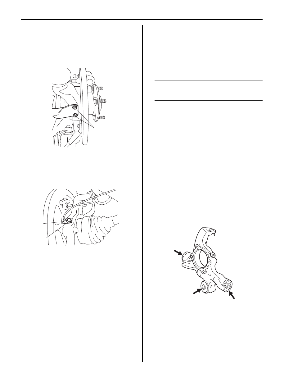
Rear Suspension Knuckle Check

S5JB0A2306024

• Inspect for cracks, deformation or damage.
• Inspect bushing for damage, wear or breakage. If any 

faulty condition is found, replace rear suspension 
knuckle assembly.

Rear Suspension Fasteners Check

S5JB0A2306025

Check each bolt and nut fastening suspension parts for 
tightness. Tighten loose one, if any, to specified torque 
referring to the figure in “Rear Suspension Construction”.

2,(a)

1

I5JB0A230074-01

1

2,(a)

I5JB0A230075-01

I5JB0A230078-01

Rear Suspension:  2C-31

Specifications

Tightening Torque Specifications

S5JB0A2307001

NOTE
The specified tightening torque is also described in the following.
“Rear Suspension Construction”
“Rear Shock Absorber and Rear Coil Spring Components”
“Rod and Arm Components”
“Rear Suspension Frame Components”
“Rear Wheel Hub Assembly and Rear Suspension Knuckle Components”


Reference:
For the tightening torque of fastener not specified in this section, refer to “Fastener Information in Section 0A”.

Fastening part

Tightening torque

Note

N

m

kgf-m

lb-ft

Control rod mount nut

135

13.5 

98.0

)

 / ) / )

Lower arm mount nut

135

13.5 

98.0

)

 / ) / ) / )

Shock absorber upper bolt

60

6.0 

43.5

)

 / ) / ) / )

Shock absorber lower bolt

90

9.0 

65.0

)

 / ) / ) / )

Wheel nut

100

10.0 72.5

)

 / ) / ) / ) / ) / ) / 

)

 / ) / ) / )

Bump stopper

50

5.0 

36.5

)

Lower arm outer bolt

135

13.5 

98.0

)

 / ) / ) / )

Parking cable hanger bolt

10

1.0 

7.5

)

Control rod outer bolt

135

13.5 

98.0

)

 / ) / )

Trailing rod mount bolt

105

10.5 76.0

)

Trailing rod mount nut

135

13.5 98.0

)

 / )

Trailing rod rear bolt

135

13.5 98.0

)

 / ) / )

Wheel sensor bolt

11

1.1 

8.0

)

 / ) / )

Upper arm mount nut

135

13.5 

98.0

)

Rear suspension frame mount bolt

135

13.5 

98.0

)

Parking cable clamp bolt

25

2.5 

18.0

)

Rear wheel hub housing bolt

50

5.0 

36.5

)

Parking cable cap nut 

11

1.1 

8.0

)

Brake pipe flare nut

16

1.6 

11.5

)

Rear axle nut

220

22.0 

159.5

)

Upper arm joint nut

55

5.5 

40.0

)

Rear brake hose bracket bolt

11

1.1 

8.0

)

2C-32 Rear Suspension: 

Special Tools and Equipment

Recommended Service Material

S5JB0A2308001

NOTE
Required service material is also described in the following.
“Rear Shock Absorber and Rear Coil Spring Components”
“Rod and Arm Components”
“Rear Suspension Frame Components”


Special Tool

S5JB0A2308002

Material

SUZUKI recommended product or Specification

Note

Grease

SUZUKI Super Grease A

P/No.: 99000–25010

)

09913–68711

09913–75510

Pinion bearing attachment

Bearing installer

)

)

 / )

09913–75520

09913–84510

Bearing installer

Bearing installer

)

)

 / )

09913–85210

09941–66010

Bearing installer

Bump stopper rubber 
wrench

)

 / )

)

 / )

09945–56510
Trailing rod bush remover
)

 / )

Wheels and Tires:  2D-1

Suspension

Wheels and Tires

General Description

Tires Description

S5JB0A2401001

The tire is of tubeless type. The tire is designed to 
operate satisfactorily with loads up to the full rated load 
capacity when inflated to the recommended inflation 
pressures.
Correct tire pressures and driving habits have an 
important influence on tire life. Heavy cornering, 
excessively rapid acceleration, and unnecessary sharp 
braking increase tire wear.

Tire Placard
The “Tire Placard” is located on the left or right door lock 
pillar and should be referred to tire information.
The placard lists the maximum load, tire size and cold 
tire pressure where applicable.

NOTE
Whether rim size and/or maximum load are 
listed or not depends on regulations of each 
country.


Inflation of Tires
The pressure recommended for any model is carefully 
calculated to give a satisfactory ride, stability, steering, 
tread wear, tire life and resistance to bruises.
Tire pressure, with tires cold, (after vehicle has set for 3 
hours or more, or driven less than one mile) should be 
checked monthly or before any extended trip. Set to the 
specifications on the “Tire Placard” located on the left or 
right door lock pillar.
It is normal for tire pressure to increase when the tires 
become hot during driving.
Do not bleed or reduce tire pressure after driving. 
Bleeding reduces the “Cold Inflation Pressure”.

Higher than recommended pressure can cause:
• Hard ride
• Tire bruising or carcass damage
• Rapid tread wear at center of tire

Unequal pressure on same axle can cause:
• Uneven braking
• Steering lead
• Reduced handling
• Swerve on acceleration

Lower than recommended pressure can cause:
• Tire squeal on turns
• Hard Steering
• Rapid and uneven wear on the edges of the tread
• Tire rim bruises and rupture
• Tire cord breakage

• High tire temperature
• Reduced handling
• High fuel consumption

Matched Tires and Wheels (Steel Type)
Tires and wheels are match mounted at the assembly 
plant.
This means that the radially stiffest part of the tire, or 
“high spot”, is matched to the smallest radius or “low 
spot” of the wheel.
This is done to provide the smoothest possible ride.
The “high spot” of the tire is originally marked by paint 
dot (1) on the outboard sidewall. This paint dot will 
eventually wash off the tire.
The “low spot” of the wheel is originally marked by paint 
dot (2) on the wheel rim-flange. Properly assembled, the 
wheel rims’ paint dot should be aligned with the tires’ 
paint dot as shown in figure.

Whenever a tire is dismounted from its wheel, it should 
be remounted so that the tire and wheel are matched. If 
the tire’s paint dot cannot be located, a line should be 
scribed on the tire and wheel before dismounting to 
assure that it is remounted in the same position.

Replacement Tires
When replacement is necessary, the original equipment 
type tire should be used. Refer to the “Tire Placard”. 
Replacement tires should be of the same size, load 
range and construction as those originally on the vehicle. 
Use of any other size or type tire may affect ride, 
handling, speedometer / odometer calibration, vehicle 
ground clearance and tire or snow chain clearance to the 
body and chassis.
It is recommended that new tires be installed in pairs on 
the same axle. If necessary to replace only one tire, it 
should be paired with the tire having the most tread, to 
equalize braking traction.

I2RH01240001-01


Content   ..  154  155  156  157   ..