Suzuki Grand Vitara JB416 / JB420. Manual - part 125


  Index      Suzuki     Suzuki Grand Vitara JB416 / JB420- service repair manual


Search            


Content   ..  123  124  125  126   ..


Suzuki Grand Vitara JB416 / JB420. Manual - part 125


1G-2 Fuel System: 

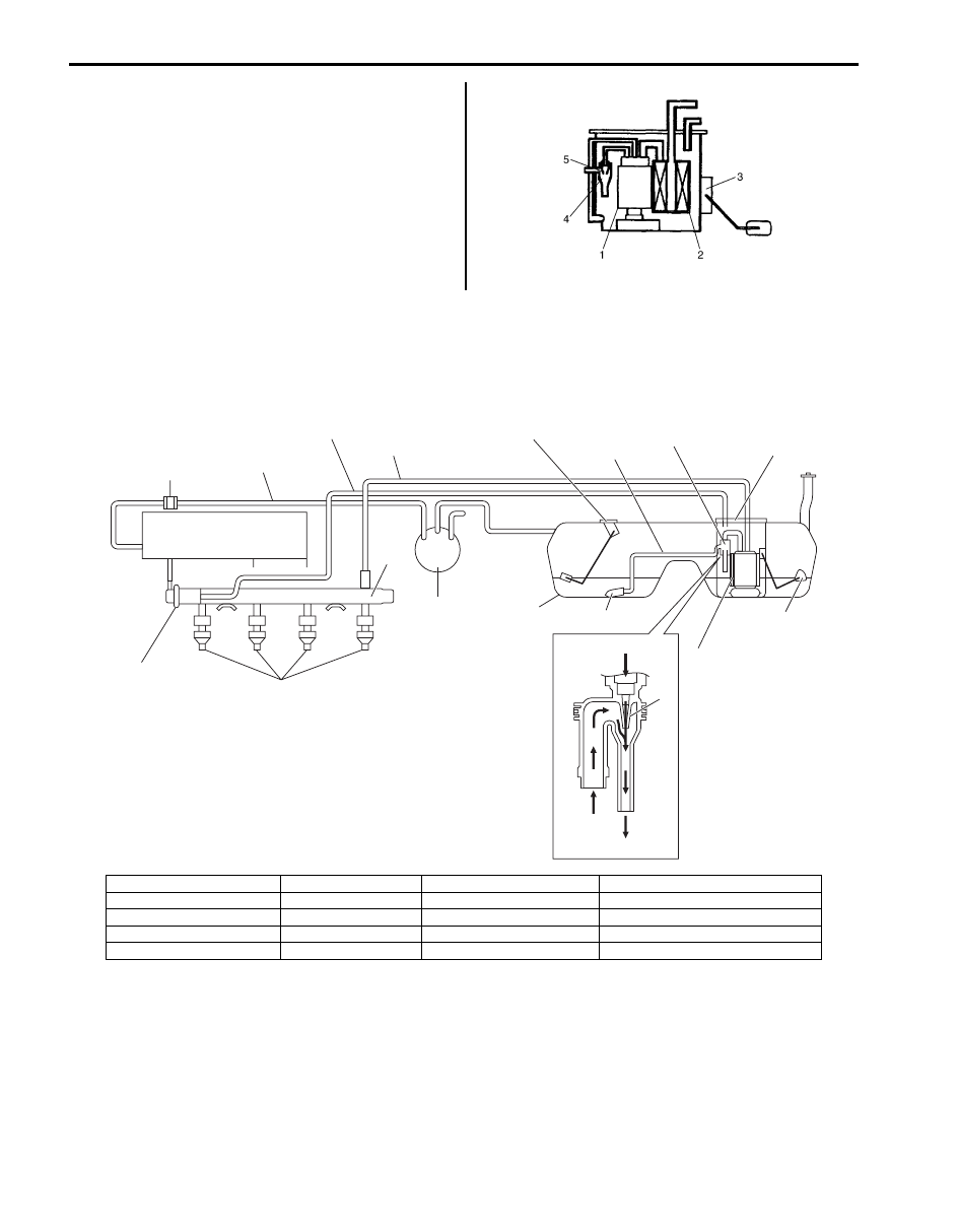
Fuel Pump Description

S5JB0A1701003

The fuel pump (1) is an in-tank type electric pump. 
Incorporated in the pump assembly are;
a fuel filter (2) included and a fuel level gauge (3) 
attached.
Also, the jet pump (4) installed in the fuel pump sucks up 
the fuel from the sub fuel level sensor side to main fuel 
level sensor side through the fuel suction pipe / hose by 
using the negative pressure produced when the part of 
pressurised fuel with the fuel pump passes the venturi 
(5).

Schematic and Routing Diagram

Fuel Delivery System Diagram

S5JB0A1702001

I5JB0A171001-03

20

7

10

6

9

13

15

14

2

12

11

19

17

18

16

1

4

5

3

8

I5JB0A171002-03

1. Fuel tank

6. Fuel feed line

11. Fuel filter

16. Fuel suction filter

2. Fuel pump

7. Fuel vapor line

12. Main fuel level sensor

17. Pressurised fuel from fuel pump

3. Fuel pressure regulator

8. Intake manifold

13. Sub fuel level sensor

18. Fuel feeded from fuel suction hose

4. Delivery pipe

9. EVAP canister

14. Jet pump

19. Venturi

5. Fuel injector

10. Fuel return line

15. Fuel suction pipe / hose

20. EVAP canister purge valve

Fuel System:  1G-3

Diagnostic Information and Procedures

Fuel Pressure Inspection

S5JB0A1704001

WARNING

!


Before starting the following procedure, be 
sure to observe “Precautions on Fuel System 
Service” 
in order to reduce the risk or fire 
and personal injury.


1) Relieve fuel pressure in fuel feed line referring to 

“Fuel Pressure Relief Procedure”.

2) Disconnect fuel feed hose from fuel delivery pipe.
3) Connect special tools and hose between fuel feed 

hose (1) and fuel delivery pipe as shown in the 
figure, and clamp hoses securely in order to ensure 
that no leaks occur during checking.

Special tool
(A):  09912–58413 
(B):  09912–58490

4) Check that battery voltage is 11 V or more.
5) Measure fuel pressure at each condition.

If measured pressure is out of specification, refer to 
“Fuel Pressure Check in Section 1A” and check each 
possibly defective part. Replace if found defective.
a) Turn ignition switch ON to operate fuel pump and 

after 2 seconds turn it OFF. Repeat this 3 or 4 
times and then check fuel pressure.

Fuel pressure specification with fuel pump 
operating and engine stopped
: 270 – 310 kPa (2.7 – 3.1 kg/cm

2

, 38.4 – 44.0 

psi)

b) Start engine and warm it up to normal operating 

temperature, and measure fuel pressure at 
idling.

Fuel pressure specification at specified idle 
speed
: 270 – 310 kPa (2.7 – 3.1 kg/cm

2

, 38.4 – 44.0 

psi)

c) Stop engine, and measure fuel pressure at one 

minute after stopping.

Fuel pressure specification with 1 min. after 
engine (fuel pump) stop (Pressure reduces 
as time passes)
For M16 engine model: Over 250 kPa (2.5 kg/
cm

2

, 35.6 psi)

For J20 engine model: Over 200 kPa (2.0 kg/
cm

2

, 28.4 psi)

[A]. For M16 engine model
[B]. For J20 engine model

[A]

[B]

(A)

(B)

(A)

(B)

I5JB0A171003-01

1G-4 Fuel System: 

6) After checking fuel pressure, remove fuel pressure 

gauge.

WARNING

!


As fuel feed line is still under high fuel 
pressure, make sure to release fuel pressure 
according to the following procedures.
• Place fuel container under joint.
• Cover joint with rag and loosen joint nut 

slowly in order to release fuel pressure 
gradually.


7) Remove special tools from fuel delivery pipe and fuel 

feed hose.

8) Connect fuel feed hose to fuel delivery pipe and 

clamp it securely.

9) With engine OFF and ignition switch ON, check for 

fuel leaks.

Fuel Cut Operation Inspection

S5JB0A1704002

NOTE
Before inspection, make sure that gear shift 
lever is in neutral position (shift select lever 
is “P” range for A/T vehicle), A/C is OFF and 
parking brake lever is pulled all the way up.


1) Warm engine up to normal operating temperature.
2) While listening to sound of injector (2) by using 

sound scope (1) or such, increase engine speed to 
higher than 3,000 r/min.

3) Check to make sure that injector operation sound is 

stop when throttle valve is closed instantly and it is 
heard again when engine speed is reduced to 
approx. 2,000 r/min or less.

I2RH01170032-01

I2RH0B170004-01

Fuel System:  1G-5

Repair Instructions

Fuel System Components

S5JB0A1706001

I5JB0A170001-03


Content   ..  123  124  125  126   ..