Suzuki Grand Vitara JB416 / JB420. Manual - part 113


  Index      Suzuki     Suzuki Grand Vitara JB416 / JB420- service repair manual


Search            


Content   ..  111  112  113  114   ..


Suzuki Grand Vitara JB416 / JB420. Manual - part 113


1D-120 Engine Mechanical: For J20 Engine

Main Bearings, Crankshaft and Cylinder Block 
Removal and Installation

S5JB0A1426041

Removal

1) Remove engine assembly from vehicle. Refer to 

“Engine Assembly Removal and Installation: For J20 
Engine”.

2) Remove clutch and flywheel (drive plate for A/T) by 

using special tool.

Special tool
(A):  09924–17810

3) Remove pistons and connecting rods referring to 

“Pistons, Piston Rings, Connecting Rods and 
Cylinders Removal and Installation: For J20 Engine”
.

4) Remove CKP sensor (1).

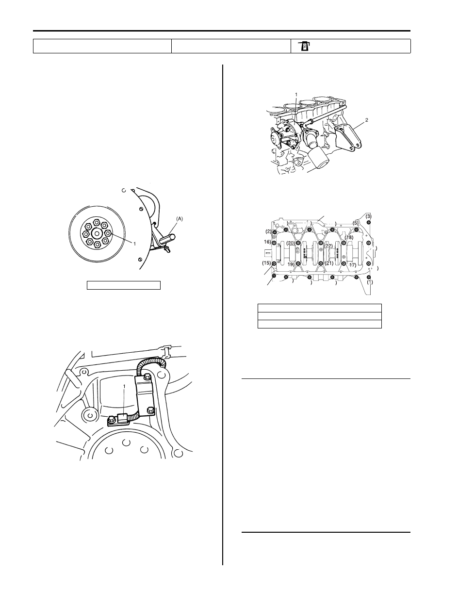
5) Remove water pump (1) and heater outlet pipe.
6) Remove engine front mounting brackets (2).

7) Loosen crankcase bolts, in sequence shown in figure 

and remove them.

8) Remove crankshaft from cylinder block.

Installation

NOTE

• All parts to be installed must be perfectly 

clean.

• Be sure to oil crankshaft journals, journal 

bearings, thrust bearings, crankpins, 
connecting rod bearings, pistons, piston 
rings and cylinder bores.

• Journal bearings, crankcase (bearings 

caps), connecting rods, rod bearings, rod 
bearing caps, pistons and piston rings are 
in combination sets. Do not disturb 
combination and try to see that each part 
goes back to where it came from, when 
installing.

• Clean mating surface of cylinder block and 

lower crankcase, remove oil, old sealant 
and dust from mating surface.


8. Rear oil seal

16. Flywheel mounting bolt

: Apply engine oil to inside / sliding 

surface.

1. Flywheel bolt

I2RH01140169-01

I2RH01140170-01

1. Lower crankcase
2. Crankcase bolts (10 mm thread diameter)
3. Crankcase bolts (8 mm thread diameter)

I2RH01140171-01

(1)

(2)

(3)

(4)

(5)

(6)

(7)

(8)

(9)

(10)

(11)

(12)

(13)

(14)

(15)

(16)

(17)

(18)

(19)

(20)

(21)

(22)

1

2

3

I4RH01140045-01

Engine Mechanical: For J20 Engine 1D-121

1) Fit main bearings to cylinder block (1).

One of two halves of main bearing (4) has oil groove 
(3).
Install this half with oil groove to cylinder block and 
another half without oil groove to lower crankcase.
Make sure that two halves are painted in the same 
color.

2) Install new O-ring (2) to cylinder block.
3) Install knock pins (5) to cylinder block.

4) Fit thrust bearings (1) to cylinder block between No.2 

and No.3 cylinders. Face oil groove (2) sides to 
crank webs.

5) Confirm that dowel pins (3) are installed to cylinder 

block.

6) Put crankshaft (1) with oil pump chain to cylinder 

block.

7) Apply sealant “A” to lower crankcase (1) mating 

surface area as shown in figure.

“A”:  Water tight sealant 99000–31250 (SUZUKI 
Bond No.1207F) 

Sealant amount for lower crankcase
Width “a”: 3 mm (0.12 in.)
Height “b”: 2 mm (0.08 in.)

8) Install lower crankcase (1) to cylinder block.

After applying engine oil to all crankcase bolts ((1) – 
(22)), tighten them gradually as follows.
a) Tighten bolts ((1) – (10)) to 30 N

⋅m (3.0 kgf-m, 

21.5 lb-ft) according to numerical order as 
shown.

b) Tighten bolts ((1) – (10)) to 42 N

⋅m (4.2 kgf-m, 

30.5 lb-ft) according to numerical order as 
shown.

c) In the same manner as in step a), tighten them to 

the specified torque.

d) Tighten bolts ((11) – (22)) to the specified torque 

according to numerical order as shown.

Tightening torque
Crankcase bolt with 10 mm thread diameter 
((1) – (10)):  Tighten 40 N

m (4.0 kgf-m, 29.0 

lb-ft), 0 N

m (0 kgf-m, 0 lb-ft), 40 Nm (4.0 kgf-

m, 29.0 lb-ft) and 58 N

m (5.8 kgf-m, 42.0 lb-ft) 

by the specified procedure.
Crankcase bolt with 8 mm thread diameter 
((11) – (22)):  Tighten 26 N

m (2.6 kgf-m, 19.0 

lb-ft) by the specified procedure.

I4RH01140055-01

I5JB0A142057-01

I2RH01140175-01

2. Bearing

I2RH01140176-01

1D-122 Engine Mechanical: For J20 Engine

NOTE

• After tightening crankcase bolts, check to 

be sure that crankshaft rotates smoothly 
when turned by hand.

• Use new crankcase bolt (10 mm thread 

diameter).


9) Pull out dowel pin (2) from crankshaft (1) and then 

install rear oil seal (3) by using special tools and 
plastic hammer.

Special tool
(A):  09911–97710
(B):  09911–97811

10) Install dowel pin (2).

11) Install CKP sensor (1) and fix its wire harness with 

bracket.

Tightening torque
CKP sensor bolt (a):  11 N·m (1.1 kgf-m, 8.0 lb-ft)

12) Install flywheel (drive plate for A/T).

Using special tool, lock flywheel or drive plate, and 
tighten flywheel or drive plate bolts (1) applied with 
sealant to specification.

Special tool
(A):  09924–17810

Tightening torque
Flywheel bolt (a):  70 N·m (7.0 kgf-m, 51.0 lb-ft)
Drive plate bolt:  65 N·m (6.5 kgf-m, 47.0 lb-ft)

13) Install engine front mounting brackets (1). Tighten 

bracket bolts to specified torque.

Tightening torque
Engine front mounting bracket bolt (a):  55 N·m (
5.5 kgf-m, 40.0 lb-ft)

14) Install water pump (2) and heater outlet pipe (3). 

Refer to “Water Pump Removal and Installation (For 
J20 Engine Model) in Section 1F”.

4. Crankshaft side

5. Oil seal side

1

I4RH01140046-01

I5JB0A142058-01

I2RH01140179-01

I2RH01140180-01

I2RH01140181-01

Engine Mechanical: For J20 Engine 1D-123

15) Install pistons and connecting rods. Refer to 

“Pistons, Piston Rings, Connecting Rods and 
Cylinders Removal and Installation: For J20 Engine”.

16) Install oil pump. Refer to “Oil Pump Removal and 

Installation: For J20 Engine in Section 1E”.

17) Install cylinder head assembly to cylinder. Refer to 

“Valves and Cylinder Head Removal and Installation: 
For J20 Engine”.

18) Install, timing chain sprockets, timing chains, timing 

chain tensioner, tensioner adjusters, timing chain 
guides, timing chain cover, crankshaft pulley, water 
pump pulley. Refer to “Timing Chain Cover Removal 
and Installation: For J20 Engine”, 
“2nd Timing Chain 
and Chain Tensioner Removal and Installation: For 
J20 Engine” an
d “1st Timing Chain and Chain 
Tensioner Removal and Installation: For J20 
Engine”.

19) Install oil pump strainer and oil pan referring to “Oil 

Pan and Oil Pump Strainer Removal and Installation: 
For J20 Engine in Section 1E”.

20) Install clutch to flywheel (for M/T vehicle). For clutch 

installation, refer to “Clutch Cover, Clutch Disc and 
Flywheel Removal and Installation in Section 5C”
.

21) Install engine assembly to vehicle. Refer to “Engine 

Assembly Removal and Installation: For J20 
Engine”.

Main Bearings, Crankshaft and Cylinder Block 
Inspection

S5JB0A1426042

Crankshaft
Crankshaft runout
Using a dial gauge, measure runout at center journal. 
Rotate crankshaft slowly. If runout exceeds its limit, 
replace crankshaft.

Limit on runout
0.06 mm (0.0023 in.)

Crankshaft thrust play
Measure this play with crankshaft set in cylinder block in 
the normal manner, that is, with thrust bearing and lower 
crankcase installed. Tighten crankcase bolts referring to 
“Main Bearings, Crankshaft and Cylinder Block Removal 
and Installation: For J20 Engine”.
Use a dial gauge to read displacement in axial (thrust) 
direction of crankshaft.
If its limit is exceeded, replace thrust bearing with new 
standard one or oversize one to obtain standard thrust 
play.

Crankshaft Thrust Play
Standard: 0.10 – 0.35 mm (0.0039 – 0.0137 in.)
Limit: 0.42 mm (0.0149 in.)

Thickness of crankshaft thrust bearing

I2RH01140182-01

Standard

2.500 mm (0.0984 in.)

Oversize: 0.125 mm 

(0.0049 in.)

2.563 mm (0.1009 in.)

1. Thrust bearing

2. Oil groove

I2RH01140183-01

I2RH01140184-01


Content   ..  111  112  113  114   ..