Suzuki Grand Vitara JB416 / JB420. Manual - part 107


  Index      Suzuki     Suzuki Grand Vitara JB416 / JB420- service repair manual


Search            


Content   ..  105  106  107  108   ..


Suzuki Grand Vitara JB416 / JB420. Manual - part 107


1D-96 Engine Mechanical: For J20 Engine

Camshafts, Tappet and Shim Removal and 
Installation

S5JB0A1426030

CAUTION

!


• Keep working table, tools and hands clean 

while overhauling.

• Use special care to handle aluminum parts 

so as not to damage them.

• Do not expose removed parts to dust.

Keep them always clean.


Removal

1) Remove 2nd timing chain. Refer to “2nd Timing 

Chain and Chain Tensioner Removal and 
Installation: For J20 Engine”
 for removal.

2) Loosen camshaft housing bolts in such order as 

indicated in figure and remove them.

3) Remove camshaft housings.
4) Remove camshafts.
5) Remove tappets with shims.

Installation

1) Apply engine oil around tappet (1), and then install 

tappets with shims to cylinder head.

NOTE
When installing shim, make sure to direct 
shim No. side toward tappet.


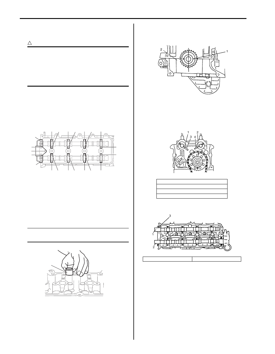
2) Match match mark (1) on crank timing sprocket and 

mating surface of cylinder block and lower 
crankcase (2).

3) Install camshafts.

Apply oil to sliding surface of each camshaft and 
camshaft journal then install them by aligning match 
marks on cylinder head and camshafts as shown in 
figure.

4) Install camshaft housing pins (3) as shown in figure.

“2”

“12” “13”

“20” “21”

“16” “17”

“6”

“10” “11”

“18” “19”

“14” “15”

“8”

“7”

“9”

“5”
“3”
“4”

“1”

I5JB0A142029-01

1

I5JB0A142030-01

1. Knock pin of intake camshaft
2. Knock pin of exhaust camshaft
3. Match mark of intake camshaft
4. Match mark of exhaust camshaft

1. Intake camshaft

2. Exhaust camshaft

I2RH01140103-01

I5JB0A142031-01

I4RH01140032-01

Engine Mechanical: For J20 Engine 1D-97

5) Check position of camshaft housings.

Embossed marks are provided on each camshaft 
housing, indicating position and direction for 
installation. Install housings as indicated by these 
marks.

6) After applying oil to housing bolts, tighten them 

temporarily first. Then tighten them by following 
numerical order in figure.
Tighten a little at a time and evenly among bolts and 
repeat tightening sequence two or three times before 
they are tightened to specified torque.

Tightening torque
Camshaft housing bolt (a):  11 N·m (1.1 kgf-m, 
8.0 lb-ft)

7) Turn crankshaft clockwise then align crankshaft 

timing sprocket key (1) with timing mark (2).

8) Install 2nd timing chain. Refer to “2nd Timing Chain 

and Chain Tensioner Removal and Installation: For 
J20 Engine” fo
r installation.

9) Install timing chain cover. Refer to “Timing Chain 

Cover Removal and Installation: For J20 Engine” for 
installation.

10) Install cylinder head cover. Refer to “Cylinder Head 

Cover Removal and Installation: For J20 Engine” for 
installation.

11) Install oil pan. Refer to “Oil Pan and Oil Pump 

Strainer Removal and Installation: For J20 Engine in 
Section 1E”
 for installation.

12) Install engine assembly to vehicle referring to 

“Engine Assembly Removal and Installation: For J20 
Engine”.

13) Check valve lashes referring to “Valve Lash 

(Clearance) Inspection: For J20 Engine”.

Camshaft, Tappet and Shim Inspection

S5JB0A1426031

Cam Wear
Using a micrometer, measure cam height. If measured 
height is below its limit, replace camshaft.

Cam height “a”

1. I: Intake side or E: Exhaust side
2. Position from timing chain side
3. Pointing to timing chain side

I2RH01140106-01

“20”, (a)

“10”, (a)

“9”, (a)

“2”, (a)

“1”, (a)

“6”, (a)

“16”, (a)

“15”, (a)

“13”, (a)

“17”, (a)
“19”, (a)
“18”, (a)

“5”, (a)

“12”, (a)

“21”, (a)

“11”, (a)

“4”, (a)

3”, (a)

“8”, (a)

“14”, (a)

“7”, (a)

I5JB0A142032-01

Cam 

height

Standard

Limit

Intake 
cam

45.669 – 45.829 mm 

(1.798 – 1.8043 in.)

45.550 mm 

(1.793 in.)

Exhaust 
cam

45.550 – 45.710 mm 
(1.7933 – 1.7996 in.)

45.430 mm 

(1.789 in.)

I5JB0A142033-01

I5JB0A142034-01

1D-98 Engine Mechanical: For J20 Engine

Camshaft Runout
Set camshaft between two “V” blocks, and measure its 
runout by using a dial gauge.
If measured runout exceeds the specified limit, replace 
camshaft.

Runout limit
0.03 mm (0.0012 in.)

Camshaft Journal Wear
Check camshaft journals and camshaft housings for 
pitting, scratches, wear or damage.
If any malcondition is found, replace camshaft or cylinder 
head with housing. Never replace cylinder head without 
replacing housings.

Check clearance by using gauging plastic. Checking 
procedure is as follows.

1) Clean housings and camshaft journals.
2) Make sure that all tappets with shims are removed 

and install camshafts to cylinder head.

3) Place a piece of gauging plastic to full width of 

journal of camshaft (parallel to camshaft).

4) Install camshaft housing.

5) Tighten camshaft housing bolts in such order as 

indicated in figure a little at a time till they are 
tightened to specified torque.

NOTE
Do not rotate camshaft while gauging plastic 
is installed.


Tightening torque
Camshaft housing bolt (a):  11 N·m (1.1 kgf-m, 
8.0 lb-ft)

6) Remove housing, and using scale (2) on gauging 

plastic envelop (1), measure gauging plastic width at 
its widest point.

Journal clearance

I2RH01140109-01

IYSQ01143105-01

Standard

Limit

0.020 – 0.074 mm (0.0008 – 

0.0029 in.)

0.12 mm (0.0047 in.)

“20”, (a)

“10”, (a)

“9”, (a)

“2”, (a)

“1”, (a)

“6”, (a)

“16”, (a)

“15”, (a)

“13”, (a)

“17”, (a)
“19”, (a)
“18”, (a)

“5”, (a)

“12”, (a)

“21”, (a)

“11”, (a)

“4”, (a)

“3”, (a)

“8”, (a)

“14”, (a)

“7”, (a)

I5JB0A142035-02

IYSQ01143107-01

Engine Mechanical: For J20 Engine 1D-99

If measured camshaft journal clearance exceeds 
limit, measure journal (housing) bore and outside 
diameter of camshaft journal. Replace camshaft or 
cylinder head assembly whichever the difference 
from specification is greater.

Camshaft journal

Wear of Tappet and Shim
Check tappet and shim for pitting, scratches, or damage.
If any malcondition is found, replace.

Measure cylinder head bore and tappet outside diameter 
to determine cylinder head-to-tappet clearance. If 
clearance exceeds limit, replace tappet or cylinder head.

Cylinder head bore and tappet outside diameter

Oil Relief Valve
Check oil relief valve for clogging and ball for being 
stuck.

Item

Standard

Camshaft journal bore 
diameter. (IN & EX) [A]

26.000 – 26.033 mm 
(1.0236 – 1.0249 in.)

Camshaft journal O.D. (IN & 
EX) [B]

25.959 – 25.980 mm 
(1.0221 – 1.0228 in.)

I5JB0A142036-01

I2RH0B140085-01

Item

Standard

Limit

Tappet outside 
diameter [A]

32.456 – 32.472 mm 

(1.2778 – 1.2784 in.)

Cylinder head bore 
[B]

32.500 – 32.525 mm 

(1.2795 – 1.2805 in.)

Cylinder head to 
tappet clearance

0.028 – 0.069 mm 

(0.0011 – 0.0027 in.)

0.15 mm 

(0.0059 in.)

I5JB0A142038-01

I2RH01140111-01


Content   ..  105  106  107  108   ..