Suzuki Grand Vitara JB416 / JB420. Manual - part 83


  Index      Suzuki     Suzuki Grand Vitara JB416 / JB420- service repair manual


Search            


Content   ..  81  82  83  84   ..


Suzuki Grand Vitara JB416 / JB420. Manual - part 83


1C-17 Engine Electrical Devices: 

Specifications

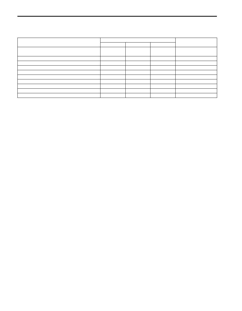
Tightening Torque Specifications

S5JB0A1307001

Reference:
For the tightening torque of fastener not specified in this section, refer to “Fastener Information in Section 0A”.

Fastening part

Tightening torque

Note

N

m

kgf-m

lb-ft

Accelerator pedal position (APP) sensor 
assembly nut

6.0

0.6 4.5

)

APP sensor assembly bracket nut

6.0

0.6 

4.3

)

ECT sensor

12.5

1.25 

9.0

)

A/F sensor 

45

4.5 

32.5

)

Heated oxygen sensor

45

4.5 

32.5

)

CMP sensor bolt 

11

1.1 

8.0

)

CKP sensor bolt

11

1.1 

8.0

)

CKP sensor bolt 

10

1.0 

7.5

)

Knock sensor

22

2.2 

16.0

)

MAF and IAT sensor screw

1.5

0.15 

1.1

)

Engine Mechanical: For M16A Engine with VVT 1D-1

Engine

Engine Mechanical

For M16A Engine with VVT

General Description

Engine Construction Description

S5JB0A1411001

The engine is water-cooled, in line 4 cylinders, 4 stroke cycle gasoline unit with its DOHC (Double overhead camshaft) 
valve mechanism arranged for “V” type valve configuration and 16 valves (4 valves / one cylinder). The double 
overhead camshaft is mounted over the cylinder head; it is driven from crankshaft through timing chain, and no push 
rods are provided in the valve train system.

I5JB0A141029-01

1D-2 Engine Mechanical: For M16A Engine with VVT

Camshaft Position Control (VVT Variable Valve Timing) System Description

S5JB0A1411002

System Description
The VVT system is an electronic control system which continuously vary and optimize the intake valve timing in 
response to the engine operating condition.
The optimized intake valve timing produce such an air intake with high efficiency that both the higher power generation 
and lower fuel consumption can be attained in the whole engine speed range from low to high. In the area of the 
average engine load, low emission of nitrogen oxides (NOx) and high fuel efficiency can also be attained by making 
the valve opening overlap between the intake and exhaust valves longer.
For the brief of the system operation, the intake valve timing is varied by the cam timing sprocket (1) which varies the 
rotational phase between the intake camshaft (3) and sprocket. The rotor (2) in the cam timing sprocket is actuated by 
switching or adjusting the hydraulic pressure applied to the chambers for the timing advancing (7) and/or retarding (6). 
To switch or adjust the hydraulic pressure appropriately, ECM operates the oil control valve (12) with detecting the 
engine speed, intake air value, throttle opening, engine coolant temperature and camshaft position (angle).

1

4

5

10

8

9

2

7

6

12

11

3

60˚ (variable angle)

Most retarded timing

Most advanced timing

Exhaust valve

Intake valve

Crank angle

Overlap of valves

V

alv

e lift

I5RW0C140002-01

4. Oil passage to chamber for timing retarding

8. Oil filter

10. Oil pan

5. Oil passage to chamber for timing advancing

9. Oil pump

11. Control signal from ECM

Engine Mechanical: For M16A Engine with VVT 1D-3

Oil Control Valve
The oil control valve switches and adjusts the hydraulic 
pressure applied to the cam timing sprocket by moving 
the spool valve (1) according to the duty pulse signals 
output from the ECM. By this operation, the intake valve 
timing is varied continuously. Signals output from the 
ECM are the duty pulse of about 240 Hz.

Cam Timing Sprocket
The cam timing sprocket is equipped with the chambers 
for timing advancing (2) and retarding (3) which are 
separated by the rotor (5). The rotor rotates receiving the 
hydraulic pressure applied to both the chambers. The 
sprocket (1) is installed on the housing (4) and the rotor 
is secured on the intake camshaft by fastening the bolts. 
Therefore, the actuation of the rotor makes the phase 
difference between the sprocket and intake camshaft.

Timing Advancing
When the duty ratio of the signal output from the ECM is 
heavy, the spool valve (4) of the oil control valve moves 
to the left (opposite direction against the coil (5)). By this 
spool valve movement, the pressurized oil (1) is led into 
the chambers for timing advancing and the oil in the 
chambers for timing retarding is drained. This operations 
actuate the rotor (3) and result in the advanced timing of 
the intake valve.

Timing Holding
When the duty ratio of the signal output from the ECM 
shows that of holding, the spool valve of the oil control 
valve is located at hold position. Because this condition 
generates no oil pressure changes in both chambers, 
the rotor is fixed at a target position.

Timing Retarding
When the duty ratio of the signal output from the ECM is 
light, the spool valve of the oil control valve moves to the 
right (head for the coil). By this spool valve movement, 
the pressurized oil is led into the chambers for timing 
retarding and the oil in the chambers for timing 
advancing is drained. This operations actuate the rotor 
and result in the retarded timing of the intake valve.

6. Seal

2. Drain

1

I5RW0C140034-01

1

2

3

4

5

6

I3RH0B140004-01

1 2

5

4

3

I5RW0C140035-01

I5RW0C140036-01

I5RW0C140037-01


Content   ..  81  82  83  84   ..