Suzuki Grand Vitara JB416 / JB420. Manual - part 69
1A-225 Engine General Information and Diagnosis:
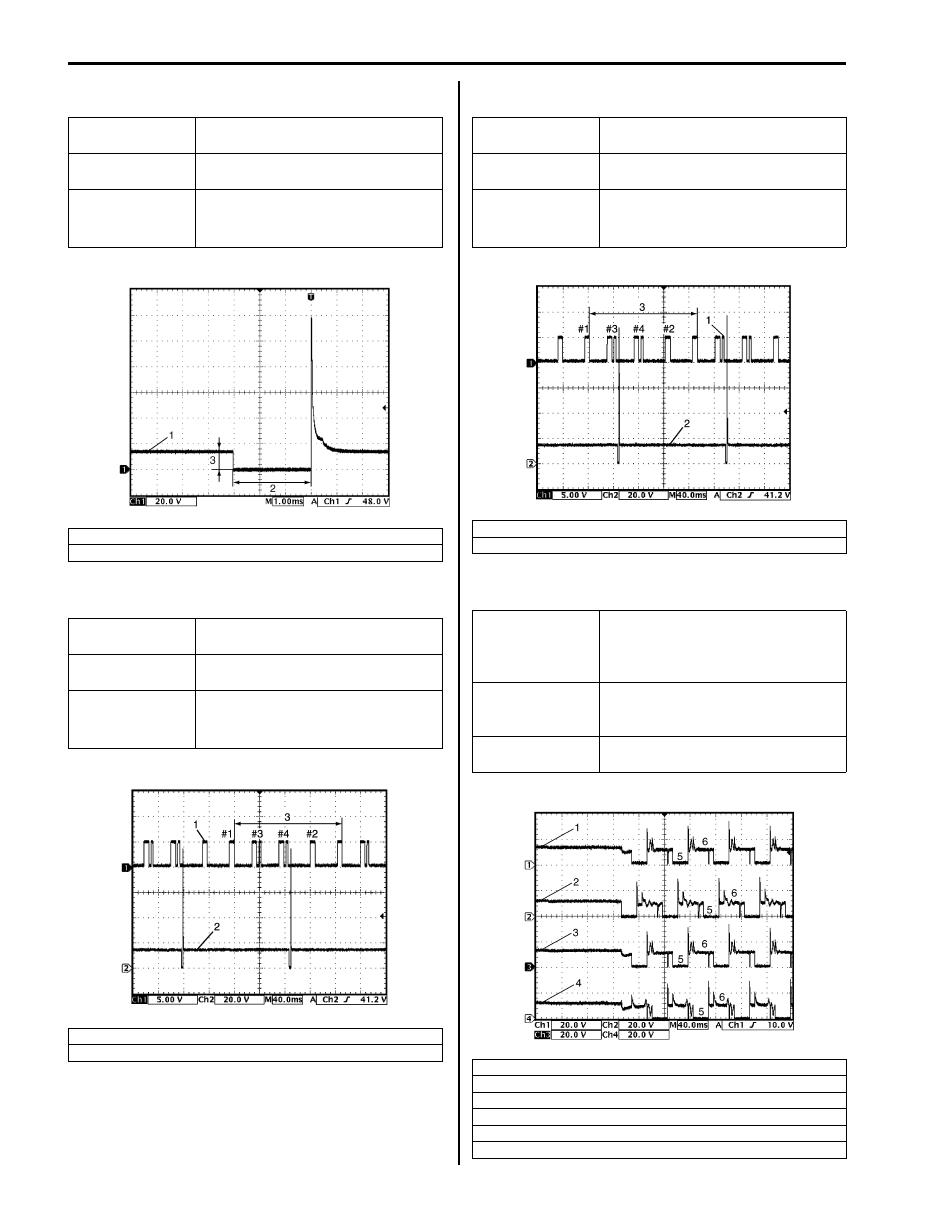
Reference waveform No.1
Fuel injector signal (1) with engine idling
Reference waveform No.2
No.1 fuel injector signal (2) with engine idling
Reference waveform No.3
No.2 fuel injector signal (2) with engine idling
Reference waveform No.4
EGR valve signal
Measurement
terminal
CH1: “C37-2” to “C37-58”
Oscilloscope
setting
CH1: 20 V/DIV
TIME: 1 ms/DIV
Measurement
condition
• After warmed up to normal
operating temperature
• Engine at specified idle speed
2. Fuel injection pulse width: 2-4 msec.
3. 10 – 14 V
Measurement
terminal
CH1: “C37-52” to “C37-58”
CH2: “C37-1” to “C37-58”
Oscilloscope
setting
CH1: 5 V/DIV, CH2: 20 V/DIV
TIME: 40 ms/DIV
Measurement
condition
• After warmed up to normal
operating temperature
• Engine at specified idle speed
1. Cylinder reference signal (CMP reference signal)
3. 720
° crank angle
I5JB0A110074-01
I5JB0A110075-01
Measurement
terminal
CH1: “C37-52” to “C37-58”
CH2: “C37-2” to “C37-58”
Oscilloscope
setting
CH1: 5 V/DIV, CH2: 20 V/DIV
TIME: 40 ms/DIV
Measurement
condition
• After warmed up to normal
operating temperature
• Engine at specified idle speed
1. Cylinder reference signal (CMP reference signal)
3. 720
° crank angle
Measurement
terminal
CH1: “C37-5” to “C37-58”
CH2: “C37-6” to “C37-58”
CH3: “C37-3” to “C37-58”
CH4: “C37-4” to “C37-58”
Oscilloscope
setting
CH1: 20 V/DIV, CH2: 20 V/DIV
CH3: 20 V/DIV, CH4: 20 V/DIV
TIME: 40 ms/DIV
Measurement
condition
Engine at cranking
1. EGR valve stepper motor coil 1 signal
2. EGR valve stepper motor coil 2 signal
3. EGR valve stepper motor coil 3 signal
4. EGR valve stepper motor coil 4 signal
5. ON signal
6. OFF signal
I5JB0A110076-01
I4RS0B110053-01