Suzuki Grand Vitara JB416 / JB420. Manual - part 21


  Index      Suzuki     Suzuki Grand Vitara JB416 / JB420- service repair manual


Search            


Content   ..  19  20  21  22   ..


Suzuki Grand Vitara JB416 / JB420. Manual - part 21


1A-33 Engine General Information and Diagnosis: 
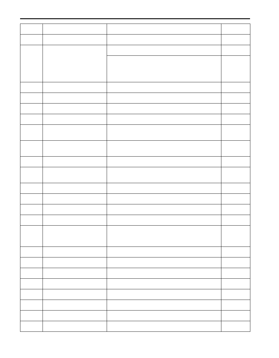
)

 *P0223

Throttle position sensor (sub) 
circuit high

Output voltage of throttle position sensor (sub) is higher 
than specification.

1 driving 

cycle

)


U*P0300

Random misfire detected

Misfire of such level as to cause damage to three way 
catalyst.

*2 driving 

cycles

)


U*P0301 / 
U*P0302 / 
U*P0303 / 

U*P0304

Cylinder 1 misfire detected
Cylinder 2 misfire detected
Cylinder 3 misfire detected
Cylinder 4 misfire detected

Misfire of such level as to deteriorate emission but not to 
cause damage to three way catalyst.

2 driving 

cycles

)

 *P0327 Knock sensor circuit low

Output voltage of knock sensor is less than specification.

1 driving 

cycle

)

 *P0328 Knock sensor circuit high

Output voltage of knock sensor is more than specification.

1 driving 

cycle

)

 *P0335

Crankshaft position sensor 
circuit

No signal of CKP sensor for specified time even if starting 
motor signal is input.

1 driving 

cycle

)

 *P0340 Camshaft position sensor circuit CMP sensor pulse is out of specification.

1 driving 

cycle

)


U*P0401

Exhaust gas recirculation flow 
detected as insufficient

Difference in intake manifold absolute pressure between 
opened EGR valve and closed EGR valve is less than 
specification.

2 driving 

cycles

)


U*P0402

Exhaust gas recirculation flow 
detected as excessive

Difference in intake manifold absolute pressure between 
opened EGR valve and closed EGR valve is more than 
specification.

2 driving 

cycles

)

 *P0403

Exhaust gas recirculation 
control circuit

Output voltage is different from output command with 
more than one pole out of 4 poles.

1 driving 

cycle

)


U*P0420

Catalyst system efficiency 
below threshold

Ratio between integrated value of A/F sensor output 
variation and integrated value of HO2S-2 output variation 
is more than specification.

2 driving 

cycles

)

 *P0443

Evaporative emission system 
purge control valve circuit

Monitor signal of EVAP canister purge valve is different 
from command signal. (circuit open or shorted to ground)

2 driving 

cycles

)

 P0462 Fuel level sensor circuit low

Circuit voltage of fuel level sensor is less than 
specification.

)

 P0463 Fuel level sensor circuit high

Circuit voltage of fuel level sensor is more than 
specification.

)

 *P0480

Fan 1 (Radiator cooling fan) 
control circuit

Monitor signal of radiator cooling fan relay is different from 
command signal.

1 driving 

cycle

)

 *P0500

Vehicle speed sensor (VSS) 
malfunction

No vehicle speed signal during fuel cut for specified time 
or longer, or vehicle speed signal is not input even if 
vehicle is driving with more than specified engine speed 
and D-range (for A/T model).

2 driving 

cycles

)


U*P0504

Brake switch “A”/“B” correlation

Brake pedal switch signal (Brake switch 2) is inconsistent 
with stop lamp switch signal (Brake switch 1).

)

 P0532

A/C refrigerant pressure sensor 
circuit low

Output voltage of A/C refrigerant pressure sensor is less 
than specification.

)

 P0533

A/C refrigerant pressure sensor 
circuit high

Output voltage of A/C refrigerant pressure sensor is more 
than specification.

)

 *P0601

Internal control module memory 
check sum error

Data write error or check sum error.

1 driving 

cycle

)

 P0602

Control module programming 
error

Data programming error.

1 driving 

cycle

)

 *P0607 Control module performance

Data programming error.

1 driving 

cycle

)


U*P0616

Starter relay circuit low

Starter signal is low voltage even though engine is started 
with vehicle at stop.

2 driving 

cycles

)


U*P0617

Starter relay circuit high

Starter signal is high voltage for specified time while 
engine is running.

2 driving 

cycles

DTC No.

Detecting item

Detecting condition

(DTC will set when detecting:)

MIL

Engine General Information and Diagnosis:  1A-34

)

 P0620 Generator control circuit

Battery voltage is higher than specification even through 
generator control is maximum regulation, or battery 
voltage is lower than specification even through generator 
control is minimum regulation and electric load is less 
than 20 A.

)

 P0625

Generator field terminal circuit 
low

Generator field coil duty is 100% (low voltage) for more 
than specified time even through generator control is 
maximum regulation, or generator field coil duty is 100% 
(low voltage) when engine is starting.

)

 P0626

Generator field terminal circuit 
high

Generator field coil duty is 0% (high voltage) for more 
than specified time even through generator control is 
minimum regulation

)

 P0660

Intake manifold tuning valve 
circuit / open (for J20 engine)

Monitor signal of intake manifold tuning vacuum solenoid 
valve is different from command signal. (circuit open or 
shorted to ground)

)

 P1501

Electric load current sensor 
circuit low (for J20 engine)

Electric load current sensor circuit voltage is lower than 
specified range.

)

 P1502

Electric load current sensor 
circuit high (for J20 engine)

Electric load current sensor circuit voltage is higher than 
specified range.

)

 *P1510

ECM backup power supply 
malfunction

Backup power voltage is no input after starting engine.

1 driving 

cycle

)

 P1603

TCM trouble code detected (for 
J20 engine)

When ECM receives a trouble code from TCM, which 
indicates that some problem occurred in sensor circuits 
and its calculated values used for operations such as idle 
speed control, engine power control and so on by TCM, 
this DTC is detected by ECM.

1 driving 

cycle

)

 P1674

CAN communication (bus off 
error)

Transmission error that is inconsistent between 
transmission data and transmission monitor (CAN bus 
monitor) data is detected more than 7 times continuously.

)

 *P1676

CAN communication (reception 
error for TCM)

Reception error of communication data for TCM is 
detected for longer than specified time continuously.

1 driving 

cycle

)

 P1678

CAN communication (reception 
error for BCM)

Reception error of communication data for BCM is 
detected for longer than specified time continuously.

)

 *P1685

CAN communication (reception 
error for ABS control module)

Reception error of communication data for ABS hydraulic 
unit / control module assembly is detected for longer than 
specified time continuously.

1 driving 

cycle

)

 *P2101

Throttle actuator control motor 
circuit range/performance

Monitor signal of throttle actuator output (duty output) is 
inconsistent with throttle actuator control command.

1 driving 

cycle

)

 *P2102

Throttle actuator control motor 
circuit low

Power supply voltage of throttle actuator control circuit is 
lower than specification even if throttle actuator control 
relay turned on.

1 driving 

cycle

)

 *P2103

Throttle actuator control motor 
circuit high

Power supply voltage of throttle actuator control circuit is 
higher than specification even if throttle actuator control 
relay turned off.

1 driving 

cycle

)

 *P2111

Throttle actuator control system 
– stuck open

Throttle valve default opening is greater than 7

° from 

complementary closed position when diagnosing throttle 
valve at ignition switch turned OFF.

1 driving 

cycle

)

 *P2119

Throttle actuator control throttle 
body range/performance

Difference between actual throttle valve opening angle 
and opening angle calculated by ECM is more than 
specification.

1 driving 

cycle

)

 *P2122

Pedal position sensor (main) 
circuit low input

Output voltage of pedal position sensor (main) is lower 
than specification.

1 driving 

cycle

)

 *P2123

Pedal position sensor (main) 
circuit high input

Output voltage of pedal position sensor (main) is higher 
than specification.

1 driving 

cycle

)

 *P2127

Pedal position sensor (sub) 
circuit low input

Output voltage of pedal position sensor (sub) is lower 
than specification.

1 driving 

cycle

)

 *P2128

Pedal position sensor (sub) 
circuit high input

Output voltage of pedal position sensor (sub) is higher 
than specification.

1 driving 

cycle

DTC No.

Detecting item

Detecting condition

(DTC will set when detecting:)

MIL

1A-35 Engine General Information and Diagnosis: 

)

 *P2135

Throttle position sensor (main / 
sub) voltage correlation

Difference between the opening angle based on throttle 
position sensor (main) and the opening angle based on 
throttle position sensor (sub) is more than specification.

1 driving 

cycle

)

 *P2138

Pedal position sensor (main / 
sub) voltage correlation

Difference between the opening angle based on 
accelerator pedal position sensor (main) and the opening 
angle based on accelerator pedal position sensor (sub) is 
more than specification.

1 driving 

cycle

)


U*P2195

O2 sensor signal stuck lean 
(Sensor-1)

A/F sensor output is lower than specification.

2 driving 

cycles

)


U*P2196

O2 sensor signal stuck rich 
(Sensor-1)

A/F sensor output is higher than specification.

2 driving 

cycles

)

 *P2227

Barometric pressure circuit 
range/performance

Difference of barometric pressure value and intake 
manifold pressure value is more than specification at 
engine start.

2 driving 

cycles

)


U*P2228

Barometric pressure circuit low

Barometric pressure sensor voltage is less than 
specification.

1 driving 

cycle

)

 *P2229 Barometric pressure circuit high

Barometric pressure sensor voltage is more than 
specification.

1 driving 

cycle

UP1614 Transponder response error

Refer to “Diagnostic Trouble Code (DTC) Table in Section 
10C”.

UP1615

ID code does not registered 
(vehicle equipped with keyless 
start system only)

Refer to “Diagnostic Trouble Code (DTC) Table in Section 
10C”.

UP1616

Different registration ID codes 
(vehicle equipped with keyless 
start system only)

Refer to “Diagnostic Trouble Code (DTC) Table in Section 
10C”.

UP1618

CAN communication error 
(reception error for keyless start 
control module) (vehicle 
equipped with keyless start 
system only)

Refer to “Diagnostic Trouble Code (DTC) Table in Section 
10C”.

UP1621

Immobilizer communication line 
error

Refer to “Diagnostic Trouble Code (DTC) Table in Section 
10C”.

UP1622 EEPROM error

Refer to “Diagnostic Trouble Code (DTC) Table in Section 
10C”.

UP1623 Unregistered transponder

Refer to “Diagnostic Trouble Code (DTC) Table in Section 
10C”.

UP1625 Immobilizer antenna error

Refer to “Diagnostic Trouble Code (DTC) Table in Section 
10C”.

P1636

Immobilizer information 
registration failure

Refer to “Diagnostic Trouble Code (DTC) Table in Section 
10C”.

P1638

Immobilizer information 
mismatched

Refer to “Diagnostic Trouble Code (DTC) Table in Section 
10C”.

DTC No.

Detecting item

Detecting condition

(DTC will set when detecting:)

MIL

Engine General Information and Diagnosis:  1A-36

For Vehicle Equipped with A/T
When using OBD generic scan tool, not only the previous star (*) marked ECM DTC(s) but also the following DTC(s) is 
displayed on OBD generic scan tool simultaneously.

Fail-Safe Table

S5JB0A1104006

When any of the following DTCs is detected, ECM enters fail-safe mode as long as malfunction continues to exist but 
that mode is canceled when ECM detects normal condition after that.

DTC No.

Detecting item

Detecting condition

(DTC will set when detecting)

*P0705 Transmission range sensor circuit malfunction (PRNDL input)

Refer to “DTC Table in Section 5A”.

*P0707 Transmission range sensor circuit low
*P0712 Transmission fluid temperature sensor circuit low
*P0713 Transmission fluid temperature sensor circuit high
*P0717 Input / Turbine speed sensor circuit no signal
*P0722 Output speed sensor circuit no signal
*P0741 Torque converter clutch circuit performance or stuck off
*P0742 Torque converter clutch circuit stuck on
*P0751 Shift solenoid-A (No.1) performance or stuck off
*P0752 Shift solenoid-A (No.1) stuck on
*P0756 Shift solenoid-B (No.2) performance or stuck off
*P0757 Shift solenoid-B (No.2) stuck on
*P0962 Pressure control solenoid control circuit low
*P0963 Pressure control solenoid control circuit high
*P0973 Shift solenoid-A (No.1) control circuit low
*P0974 Shift solenoid-A (No.1) control circuit high
*P0976 Shift solenoid-B (No.2) control circuit low
*P0977 Shift solenoid-B (No.2) control circuit high
*P1702 Internal control module memory check sum error
*P1774 Control module communication bus off
*P1777 TCM lost communication with ECM (Reception error)
*P1874 4L switch circuit malfunction (Short)
*P1875 4L switch circuit malfunction (Open)
*P2763 Torque converter clutch pressure control solenoid control circuit high
*P2764 Torque converter clutch pressure control solenoid control circuit low

DTC No.

Detected item

Fail-safe operation

)

 P0030

HO2S heater control circuit (Sensor-1)

ECM stops air/fuel ratio control.

)

 P0031

HO2S heater control circuit low (Sensor-1)

)

 P0032

HO2S heater control circuit high (Sensor-1)

)

 P0102

Mass air flow circuit low input

• ECM controls injector drive time (fuel injection 

volume) according to throttle valve opening 
(closed throttle position or not).

• ECM stops EGR control.

)

 P0103

Mass air flow circuit high input

)

 P0112

Intake air temperature sensor circuit low

ECM controls actuators assuming that intake air 
temperature is 20 

°C (68 °F).

)

 P0113

Intake air temperature sensor circuit high

)

 P0117

Engine coolant temperature circuit low

• ECM controls actuators assuming that engine 

coolant temperature is 80 

°C (176 °F).

• ECM operates radiator cooling fan.

)

 P0118

Engine coolant temperature circuit high

)

 P0122

Throttle position sensor (main) circuit low

• ECM turns off throttle actuator control relay and 

throttle valve is fixed at the opening of about 7° 
from its completely closed position (default 
opening).

• ECM controls fuel cut at specified engine speed.
• ECM stops air/fuel ratio control.


Content   ..  19  20  21  22   ..