Suzuki: Engine K6A-YH6. Manual - part 20
7-34
REPAIR
7
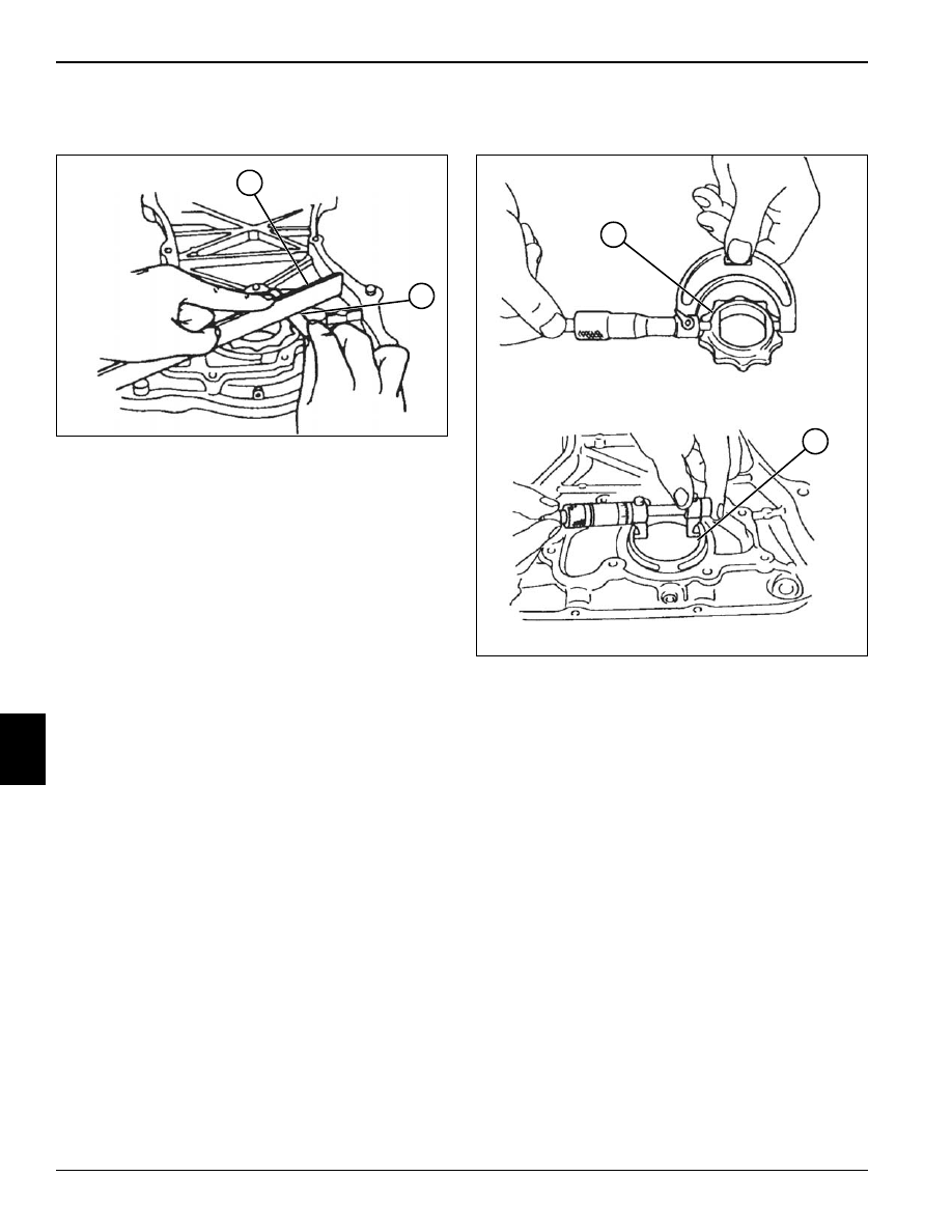
Outer Rotor Side Clearance
Figure 7-81
1.
Place a straightedge (1) across the oil pump rotor
bore. Use a feeler gauge (2) to measure the
clearance between the straightedge and the outer
rotor side surface. If measurement is beyond service
limit, replace the oil pump assembly.
Oil Pump Outer Rotor Side Clearance Limit:
0.003—0.005 in. (0.076—0.127 mm)
Inner Rotor and Pump Case Clearance
Figure 7-82
1.
Using a micrometer, measure the outside diameter of
the inner rotor shoulder (1).
2.
Measure the inside diameter of the oil pump bore
hole (2). If measurements are not within service limit,
replace oil pump assembly.
Inner Rotor and Pump Case Clearance:
0.001—0.003 in. (0.025—0.076 mm)
TN0392
1
2
TN0394
1
2