SAAB 9000. Manual - part 52


  Index      Saab     SAAB 9000 4-cyl 1985 to 1998 (C to S registration) - Service and Repair Manual


Search            copyright infringement  


Content   ..  50  51  52  53   ..


SAAB 9000. Manual - part 52


11 •24 Bodywork and fittings

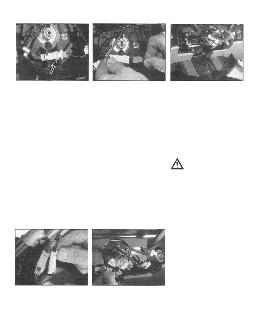
28.17a Prise the horn cable connector out

of the mounting bracket on the steering

wheel casting (arrowed)...

9 Prise out the plastic caps from the retaining
screws on the lower front panel, then remove
the screws.
10 Pull the lower panel away from the facia,
releasing the clips one at a time.
11 Unplug the airbag module wiring at the
connector.
12 Remove the four airbag module retaining
screws, then reach inside the facia, grasp the
module from behind and carefully draw it out,
whilst releasing it from the mounting clips.

Refitting

13 Refit the airbag by reversing the removal
procedure; observe the specified torque
wrench setting when tightening the airbag and
lower cover panel retaining screws.
14 Reconnect the battery negative cable, and
turn the ignition switch to the "Drive" or "Start"
position. Check the condition of the system by
observing the SRS warning light; refer to the
"General Information" sub-section to interpret

the results obtained.

Steering wheel rotary contact unit

Removal

15 Disconnect the battery negative cable,
and wait at least twenty minutes before
progressing any further; refer to the Warnings
listed in the "General Information" sub-section

for more detail.

28.17b  . . . and unplug it, labelling the cable

to aid refitting later

16 Remove the driver's airbag module, as
described earlier in this Section.
17 Prise the horn cable connector out of the
mounting bracket on the steering wheel

casting and unplug it, labelling the cable to aid
refitting later (see illustrations).
18
 Set the steering in the straight-ahead
position, then refer to Chapter 10 and remove

the steering wheel, feeding the cable
connectors through the hole in the steering
wheel casting.

19 Remove the retaining screws, and lift the
upper and lower cowling panels away from the
steering column (see illustration).

20 Unplug the contact unit and horn cables at
the connectors, after cutting through the
cable-tie securing them to the ignition
switch/lock assembly (see illustration). Label
the cables, to aid refitting later.
21 Slacken and withdraw the retaining
screws, then lift the contact unit off the
steering column (see illustration). Take great
care to ensure that the two halves of the
contact unit are not rotated whilst it is
separated from the steering column.

Refitting

22 Guide the contact unit onto the steering
column, then refit and tighten the retaining
screws.
23 Plug the horn and contact unit connectors

28.20 Unplug the contact unit and horn

cables at the connectors, after cutting

through the cable-tie securing them to the

ignition switch/lock assembly

28.21 Slacken and withdraw the retaining

screws, then lift the contact unit off the

steering column

28.19 Removing the lower cowling panel

from the steering column

together, then secure them to the ignition
switch/lock assembly with a cable-tie.
24 Refit the upper and lower steering column
cowling panels, and tighten the retaining
screws.
25 Align the contact unit with the steering
wheel as follows. Check that the front
roadwheels are still in the straight-ahead
position. Rotate the upper section of the
contact unit fully anti-clockwise, until it is felt

to touch its end stop. Note: Ensure that the
direction indicator stalk is in the "off" position,
otherwise the cancelling mechanism may
affect the alignment accuracy.

Caution: Do not apply excessive
force during this operation; the
contact unit has very fragile
internal components. Now rotate

the contact unit clockwise by the number
of turns printed on the unit's label (either

2.5 or 3.5 turns) - ensure that the unit is
now kept in this position until the steering

wheel is refitted.

26 Offer up the steering wheel to the steering
column, and feed the cable connectors
through the hole in the wheel casting. Engage
the spigot protruding from the contact unit
with the alignment hole in the steering wheel
casting - ensure that the wheel is fitted
squarely in the straight-ahead position; the
contact unit may be rotated slightly to allow

the alignment spigot to engage, if necessary.
27 Fit a new steering wheel centre nut and
tighten it to the specified torque, referring to
Chapter 10 for details.
28 Plug together the horn cable connector,
and then press the connector housing into the
mounting provided in the steering wheel
casting.
29 Refit the airbag, as described earlier in this
Section.
30 Reconnect the battery negative cable, and
turn the ignition switch to the "Drive" or "Start"

position. Check the condition of the system by
observing the SRS warning light; refer to the
"General Information" sub-section to interpret

the results obtained.

Chapter 12 Body electrical systems

Contents

Anti-theft alarm - general information 20
Cigarette lighter - removal and refitting 11
Clock/trip computer module - removal and refitting 10
Electrical fault-finding - general information 2
Exterior light bulbs - renewal 7
Exterior light units - removal and refitting 6
Fuses and relays - general information 3
General information 1
Headlight beam adjustment - general information 8
Heated front seat components - general information 21
Horn components - removal and refitting 13
In-car entertainment components - general information 17
Instrument panel - removal and refitting 9

Interior light bulbs - removal and refitting 5
Loudspeakers - removal and refitting 18
Radio aerial (electric) - removal and refitting .... 19

Speedometer drive cable - renewal 12
Switches and controls - removal and refitting 4
Tow bar - general information 22
Windscreen, tailgate and headlight wiper arms - removal and

refitting 14

Windscreen, tailgate and headlight wiper motor and linkage -

removal and refitting 15

Windscreen, tailgate and headlight washer system components -

removal and refitting 16

Specifications

Bulb ratings Watts

Courtesy lights 5

Direction indicator, rear 21
Direction indicator, front/parking light 21/5
Direction indicator side repeaters 5
Door courtesy/warning lights 5
Engine bay light 15
Facia light 5
Foglight, rear/tail light 21/4

Glovebox light . • 5
Headlight, H4 holder (single-reflector) 60/55
Headlight, H1 holder (double-reflector) 55

Bulb ratings Watts

High-level brake light:

Inner pair of bulbs 3
Outer pair of bulbs 5

Luggage area light 10
Map reading lights 5
Number plate light 5
Parking light 4
Reversing lights 21
Seat belt warning light 5
Stop-lights 21

Tail light .........4

This Chapter covers all electrical systems

not directly related to the vehicle's powertrain.
The starting, charging and ignition systems are
covered in Chapter 5, Parts A and B.

Refer to the precautions listed in "Safety

first!", before commencing any of the
operations detailed in this Chapter.

Caution: Electronic Control Units

(ECUs) contain components that
are sensitive to the levels of static
electricity generated by a person

during normal activity. Once the multi-plug
connector has been unplugged, the exposed
ECU connector pins can freely conduct
stray static electricity to these components,
damaging or even destroying them - the
damage will be invisible, and may not
manifest itself immediately. Expensive
repairs can be avoided by observing the
following basic handling rules:

a) Handle a disconnected ECU by its case

only; do not allow fingers or tools to come
into contact with the pins.

b) When carrying an ECU around, "earth"

yourself from time to time, by touching a

metal object such as an unpainted water
pipe, this will discharge any potentially-
damaging static that may have built up.

c) Do not leave the ECU unplugged from its

connector for any longer than is absolutely
necessary.

Note: Refer to the precautions given in "Safety
first!" and in Section 1 of this Chapter before
starting work. The following tests relate to
testing of the main electrical circuits, and
should not be used to test delicate electronic
circuits (such as anti-lock braking systems),

particularly where an electronic control unit

(ECU) is involved.

General

1 A typical electrical circuit consists of an
electrical component, any switches, relays,
motors, fuses, fusible links or circuit breakers
related to that component, and the wiring and
connectors which link the component to both

the battery and the chassis. To help to

pinpoint a problem in an electrical circuit,

wiring diagrams are included at the end of this
manual.
2 Before attempting to diagnose an electrical
fault, first study the appropriate wiring
diagram, to obtain a more complete
understanding of the components included in
the particular circuit concerned. The possible
sources of a fault can be narrowed down by
noting whether other components related to
the circuit are operating properly. If several
components or circuits fail at one time, the

problem is likely to be related to a shared fuse
or earth connection.

3 Electrical problems usually stem from
simple causes, such as loose or corroded
connections, a faulty earth connection, a

12•1

Degrees of difficulty

12•2 Body electrical systems

blown fuse, a melted fusible link, or a faulty
relay (refer to Section 3 for details of testing
relays). Visually inspect the condition of all
fuses, wires and connections in a problem
circuit before testing the components. Use the
wiring diagrams to determine which terminal
connections will need to be checked, in order

to pinpoint the trouble-spot.
4 The basic tools required for electrical fault-
finding include: a circuit tester or voltmeter (a

12-volt bulb with a set of test leads can also
be used for certain tests), a self-powered test
light (sometimes known as a continuity tester),
an ohmmeter (to measure resistance), a
battery and set of test leads, and a jumper

wire, preferably with a circuit breaker or fuse
incorporated, which can be used to bypass
suspect wires or electrical components.
Before attempting to locate a problem with
test instruments, use the wiring diagram to
determine where to make the connections.
5 To find the source of an intermittent wiring
fault (usually due to a poor or dirty connection,
or damaged wiring insulation), an integrity test
can be performed on the wiring, which
involves moving the wiring by hand, to see if
the fault occurs as the wiring is moved. It
should be possible to narrow down the source
of the fault to a particular section of wiring.
This method of testing can be used in
conjunction with any of the tests described in
the following sub-Sections.
6 Apart from problems due to poor
connections, two basic types of fault can
occur in an electrical circuit - open-circuit, or
short-circuit.
7 Open-circuit faults are caused by a break
somewhere in the circuit, which prevents
current from flowing. An open-circuit fault will
prevent a component from working, but will
not cause the relevant circuit fuse to blow.

8 Short-circuit faults are caused by a "short"
somewhere in the circuit, which allows the
current flowing in the circuit to "escape" along
an alternative route, usually to earth. Short-
circuit faults are normally caused by a
breakdown in wiring insulation, which allows a
feed wire to touch either another wire, or an
earthed component such as the bodyshell. A
short-circuit fault will normally cause the
relevant circuit fuse to blow. Note: A short-
circuit that occurs in the wiring between a
circuit's battery supply and its fuse will not
cause the fuse in that particular circuit to blow.
This part of the circuit is unprotected - bear
this in mind when fault-finding on the vehicle's

electrical system.

Finding an open-circuit

9 To check for an open-circuit, connect one
lead of a circuit tester or voltmeter to either the
negative battery terminal or a known good
earth.
10 Connect the other lead to a connector in
the circuit being tested, preferably nearest to
the battery or fuse.
11 Switch on the circuit, bearing in mind that

some circuits are live only when the ignition
switch is moved to a particular position.
12 If voltage is present (indicated either by

the tester bulb lighting or a voltmeter reading,
as applicable), this means that the section of
the circuit between the relevant connector and
the battery is problem-free.

13 Continue to check the remainder of the

circuit in the same fashion.

14 When a point is reached at which no

voltage is present, the problem must lie
between that point and the previous test point
with voltage. Most problems can be traced to
a broken, corroded or loose connection.

Finding a short-circuit

15 To check for a short-circuit, first

disconnect the load(s) from the circuit (loads
are the components which draw current from
a circuit, such as bulbs, motors, heating
elements, etc).

16 Remove the relevant fuse from the circuit,
and connect a circuit tester or voltmeter to the

fuse connections.

17 Switch on the circuit, bearing in mind that
some circuits are live only when the ignition
switch is moved to a particular position.
18 If voltage is present (indicated either by

the tester bulb lighting or a voltmeter reading,
as applicable), this means that there is a short-
circuit.
19 If no voltage is present, but the fuse still
blows with the load(s) connected, this
indicates an internal fault in the load(s).

Finding an earth fault

20 The battery negative terminal is connected
to "earth" - the metal of the engine/
transmission and the car body - and most
systems are wired so that they only receive a
positive feed, the current returning via the
metal of the car body. This means that the
component mounting and the body form part
of that circuit. Loose or corroded mountings
can therefore cause a range of electrical faults,
ranging from total failure of a circuit, to a
puzzling partial fault. In particular, lights may
shine dimly (especially when another circuit
sharing the same earth point is in operation),
motors (eg wiper motors or the radiator cooling

fan motor) may run slowly, and the operation of
one circuit may have an apparently-unrelated
effect on another. Note that on many vehicles,
earth straps are used between certain
components, such as the engine/transmission
and the body, usually where there is no metal-
to-metal contact between components, due to
flexible rubber mountings, etc.
21 To check whether a component is properly
earthed, disconnect the battery, and connect
one lead of an ohmmeter to a known good
earth point. Connect the other lead to the wire
or earth connection being tested. The
resistance reading should be zero; if not,
check the connection as follows.
22 If an earth connection is thought to be

faulty, dismantle the connection, and clean

back to bare metal both the bodyshell and the

wire terminal, or the component's earth
connection mating surface. Be careful to
remove all traces of dirt and corrosion, then use
a knife to trim away any paint, so that a clean
metal-to-metal joint is made. On reassembly,
tighten the joint fasteners securely; if a wire
terminal is being refitted, •use serrated washers
between the terminal and the bodyshell, to
ensure a clean and secure connection. When
the connection is remade, prevent the onset of
corrosion in the future by applying a coat of
petroleum jelly or silicone-based grease, or by
spraying on (at regular intervals) a proprietary
ignition sealer or a water-dispersant lubricant.

Fuses

1 Fuses are designed to break an electrical
circuit when a predetermined current limit is
reached, in order to protect the components
and wiring which could be damaged by
excessive current flow. Any excessive current

flow will be due to a fault in the circuit, usually
a short-circuit (see Section 2).
2 The main fuses are located in the fusebox,
which is mounted behind a drop-down panel
inside the glovebox. The fusebox also serves
as a distribution board for the different
sections of the vehicle's harness.
3 To gain access to the fusebox, open the
glovebox, then press and release the top of
the fusebox panel, allowing it to flip open.
4 Additional fuses are housed in the auxiliary
fusebox, which is mounted in the engine bay,
in front of the battery (see illustration). On
certain models, fuses specific to the ABS and

TCS systems are housed in a dedicated
fusebox, mounted in the engine bay on the

bulkhead, adjacent to the brake fluid reservoir.
5 To remove a fuse, first ensure that the
relevant circuit is switched off. If in doubt,
disconnect the battery negative cable to
isolate the supply.

6 Using the plastic tool provided in the
fusebox, pull the fuse from its socket.

3.4 Auxiliary fusebox

Body electrical systems 12•3

3.7 A blown fuse can be recognised by its

melted or broken wire

7 Inspect the fuse from the side, through the
transparent plastic body - a blown fuse can be
recognised by its melted or broken wire (see
illustration).
8
 Spare fuses are provided in the blank
terminal positions in the fusebox.
9 Before renewing a blown fuse, trace and
rectify the cause, and always use a fuse of the
correct rating. Never substitute a fuse of a
higher rating, or make temporary repairs using
wire or metal foil; more serious damage, or
even a fire, could result.
10 Note that the fuses are colour-coded, as
described below - refer to the wiring diagrams
for details of the fuse ratings and the circuits
protected.

Colour Rating
Orange 5A

Red 10A

Blue 15A

Yellow 2OA
Clear or white 25A
Green 3OA

Relays

11 A relay is an electrically-operated
mechanical switch, which may be used for the
following reasons:

a) A relay can switch a heavy current remotely

from the circuit in which the current is
flowing, therefore allowing the use of
lighter-gauge wiring and switch contacts.

b) A relay can receive more than one control

input, unlike a mechanically-operated
switch.

3.12 Removing the main fusebox to gain

access to the main relay panel

c) Relays are available with internal timing

components, to provide a time delay
function - for example, the intermittent
wiper relay and direction indicator flasher
module.

12 The main relays are mounted on a panel
behind the main fusebox. To gain access to it,
remove the glovebox as described in the
relevant paragraphs of Chapter 11, Sec-

tion 27, then remove the retaining screws and

lift the fusebox away from the bulkhead
mountings (see illustration).
13
 Additional relays are located in an auxiliary

fusebox mounted in the engine bay, in front of
the battery tray (refer to illustration 3.4).

14 Relays specific to the ABS and TCS
systems are housed in a dedicated fusebox,
mounted in the engine bay on the bulkhead,
adjacent to the brake fluid reservoir.
15 If a circuit or system that is controlled by a
relay develops a fault and the performance of

the relay is in doubt, switch on the system in
question. In general, if the relay is functioning,

it should be possible to hear it "click" as it is

energises. If this is found to be the case, then
it is probable that the fault lies with the
system's components or wiring. If the relay
cannot be heard to energise, then either the
relay is not receiving a main supply or
switching voltage, or the relay itself is faulty.
Verification can be carried out by the
substitution of a known good unit, but be
careful - while some relays are identical in
appearance and operation, others look similar

but perform different functions - ensure that

the substitute relay is of exactly the same
type.

16 To remove a relay, first ensure that the
relevant circuit is switched off. The relay can

then simply be pulled out from the socket, and

pushed back into position. Note that some of

the more heavy-duty relays may be secured in

position by a retaining screw.

Warning: To eliminate the risk of

causing accidental short-circuits,
disconnect the battery negative
cable, and position it away from

the terminal, before attempting any of the
following operations.

Ignition switch/steering column
lock

1 Refer to Chapter 10.

Steering column combination

switches

Removal

Note: It is possible to remove the combination

switches without having to remove the
steering wheel - it is sufficient just to remove

the column shrouds. However, we removed
the steering wheel for clarity.
2 Refer to Chapter 10 and remove the
steering wheel.
3 Remove the three retaining screws, and lift
the switch assembly away from the steering
column (see illustration).

4 Label the cables leading to the switch
assembly to aid refitting later, then unplug the

multi-plug connectors.
5 Remove the two screws at the base of each
switch module, and separate them from the
mounting bracket (see illustrations).
Refitting

6 Refit the switches by reversing the removal

procedure.

Headlight height adjustment switch,
instrument panel illumination
control, seat heater controls

Removal

7 These switches are all encased in modules

4.3 Remove the three retaining screws, and

lift the switch assembly away from the

steering column

4.5a Remove the two screws (arrowed) at

the base of each switch module  . . .

4.5b  . . . and separate them from the

mounting bracket


Content   ..  50  51  52  53   ..