SAAB 9000. Manual - part 30
5A•6 Starting and charging systems
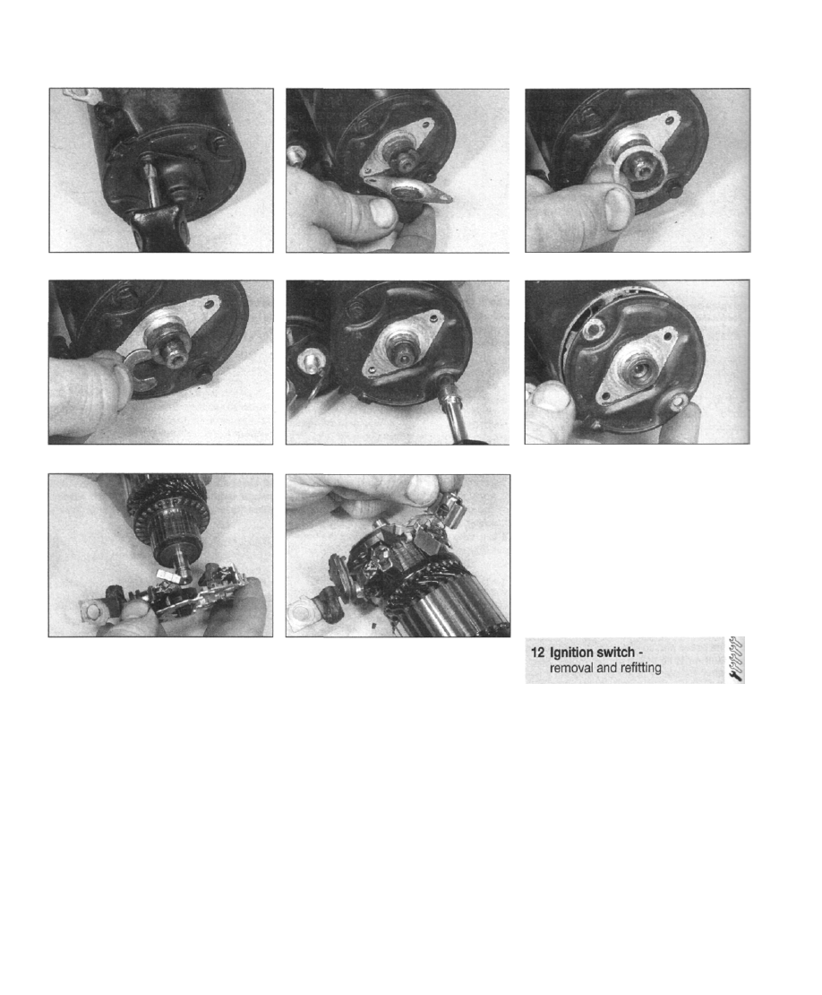
11.3a Remove the screws ...
11.3b ... lift off the cover...
11.4 Removing the circlip and shims
11.5 Unscrew the through-bolts . . .
11.7 Removing the brush holder assembly
3 Unscrew and remove the two screws
securing the cover to the end bracket. Lift off
the cover and remove the seal (see
illustrations).
4 Extract the circlip, and remove the shim(s)
and O-ring seal (see illustration).
5 Unscrew the through-bolts securing the
commutator end bracket and yoke to the
pinion end bracket (see illustration). Mark the
end bracket in relation to the yoke.
6 Remove the commutator end bracket (see
illustration).
7 Withdraw the brush holder assembly, at the
same time releasing the feed cable grommet
from the yoke. If the commutator/armature
requires attention or cleaning, withdraw it from
the yoke at this stage, then remove the brush
holder assembly (see illustration). As the
holder assembly is removed, the brushes will
be pushed out of their holders by the springs,
but will be retained by the leads.
8 Check the brushes for wear, and renew as
necessary. It may be possible to obtain
11.9 Fitting the brush holders
individual brushes from a motor factor,
otherwise the complete brush holder may
have to be renewed. Clean all the components
before reassembly. Clean the commutator
using fine glasspaper. If it is worn excessively,
it may be possible to have it machined by an
auto-electrician. Make sure that the brush
holders are thoroughly cleaned, so that the
new brushes will move freely in them.
9 Locate the brush plate without the brush
holders part-way onto the commutator, then
centralise the brushes, and fit the holders and
springs over the brushes (see illustration).
10 If removed, refit the armature inside the
yoke.
11 Slide the complete bush holder assembly
onto the armature commutator, while guiding
the feed cable grommet in the yoke slot.
12 Locate the commutator end bracket on
the armature, followed by the O-ring seal,
shim(s) and circlip. Make sure that the O-ring
seal is correctly fitted.
13 Refit the end bracket, making sure that the
11.3c . . . and remove the seal
11.6... and remove the commutator end
bracket
mark is aligned with the previously-made mark
on the yoke. Insert and tighten the through-
bolts.
14 Refit the shims and circlip, then refit the
cover and seal to the end bracket, and tighten
the two screws.
15 Reconnect the feed cable to the solenoid
terminal, and tighten the nut.
16 Refit the starter motor with reference to
Section 10.
Removal
1 Refer to Chapter 10 and remove the ignition
switch/steering column lock.
2 To remove the ignition switch, unscrew the
socket-headed screws, and withdraw the
switch from the lock housing.
3 The lock cylinder may be removed by first
inserting the ignition key and turning it to
position "1". Using a suitable instrument
through the hole provided, depress the locking
tab, then withdraw the lock cylinder from the
housing.
Refitting
4 To refit the lock cylinder, push it into the
housing until the locking tab is engaged.
5 Locate the ignition switch on the housing,
and tighten the two socket-headed screws.
6 Refer to Chapter 10 for details of refitting
the ignition switch/steering column lock.