Dacia SuperNova (engine E7J). Manual - part 166


  Index      Dacia     Dacia SuperNova (engine E7J) - service repair manual 2004 year


Search            


Content   ..  164  165  166  167   ..


Dacia SuperNova (engine E7J). Manual - part 166


89B

ELECTRIC DIAGRAMS

89B - 8

( after 01.06.2001)

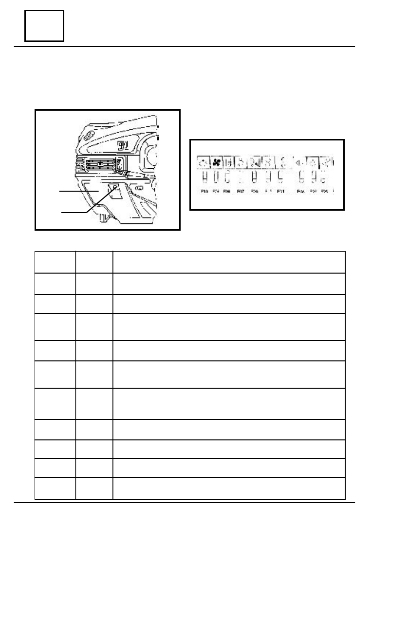
The cockpit fuse box is placed left side under dashboard, being attached on the interior side

of the door(1). To access the fuses, turn the knob (2), then open up the door towards exterior.

The fuses are protecting the following electric circuits:

FUSE

NUMBER

FUSE
TYPE

PROTECTED CIRCUIT

Clock, radio, STOP contact, climate blower relay control

Reverse driving contact

UCE decoder, speed transducer, instrument panel supply, diagnostic

socket, AC starting button, UCE anti-intrusion

Hazard and turning signaling lights

Front/rear parking lights, lighting: switches, instrument panel, climate

control, documents compartment, lighter, ashtray, radio.

Lighter, clock, instrument panel ( anti-starting indicator), front right

ceiling lamp, UCE anti-intrusion, a

nti-intrusion indicator, diagnostic socket.

UCE decoder, FLASH relay, anti-starting bushing

Rear window defrosting

Climate blower

Left fog lamp

F01

F02

F03

F04

F05

F06

F07

F08

F09

F10

15A

  5A

15A

7,5A

  5A

15A

15A

20A

15A

  5A

1

2

COCKPIT FUSE BOX

89B

ELECTRIC DIAGRAMS

89B - 9

On the fuse box, 6 fusible fuse modules are attached, protecting the following consumers:

FUSE

NUMBER

  FUSE TYPE

PROTECTED CIRCUIT

Left road lights

Right road lights, road lights indicator

Left meeting lights

Right meeting lights, meeting lights indicator

Windscreen wiper-washing switch,

windscreen wiper timer

Radio, windscreen wiper motor

    10A

    10A

    10A

    10A

    15A

    10A

F11

F12

F13

F14

F15

F16

COCKPIT FUSE BOX

89B

ELECTRIC DIAGRAMS

89B -  10

FUSE BOX ELECTRIC DIAGRAM

Connector C0

1. Fog lamp switch 

 fog lamp relay control

2. Parking lights 

 inlet fuse F  1

3. Outlet fuse F10 

 left fog lamp

Connector C1

1. Outlet fuse   F01 

 climate blower relay control

2. Outlet F09 

 climate blower

Connector C2

A1. Rear window defrosting switch 

 rear window defrosting timer control

A2. Mass
A3. Outlet fuse F06
B1. Outlet fuse F09 

 rear window defrosting

B2. Free
B3. Outlet fuse 07 

 UCE decoder, anti-starting bushing, FLASH relay

      Connector C3
A1. Lights switch ( + parking) 

 inlet fuse F05

A2. Outlet fuse F05 

 + parking

A3. Free
A4. Free
B1. Mass
B2. Mass
B3. Turning lights switch ( signaling relay control )
B4. Free

COCKPIT FUSE BOX

89B

ELECTRIC DIAGRAMS

89B -  11

Connector C4

A1. Anti-theft mechanism ( position M) 

  inlet fuse F03)

A2. Outlet fuse F01
A3. Hazard switch 

 inlet fuse F04,  supply of  the rear  window defrosting timer

B1. Outlet fuse F03
B2. Anti-theft mechanism (position M) 

 inlet fuse F02

B3. Outlet fuse F02 

 reverse driving contact

I = DC ( after contact )

J = IC ( before contact)

R1 = fog lamp control relay
R2 = climate blower control relay
RT = rear window defrosting timer
RS = turning signaling relay.

COCKPIT FUSE BOX


Content   ..  164  165  166  167   ..