Dacia Solenza (engine E7J). Manual - part 87
36
STEERING ASSEMBLY
36 - 15
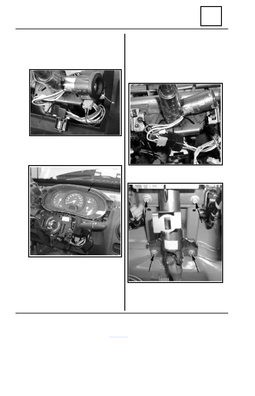
Steering column
For vehicles equipped with central
locking:
- disconnect the central locking
connector.
Dismount the anti-starting bushing (11).
Dismount the instrument panel attachment
screws.
Disconnect the four connectors of the
instrument panel.
Dismount the instrument panel.
Dismount the aerating tube from the left side
aerator as well as from the central climate
maintenance unit.
In the engine compartment:
Dismount the expansion vessel attachemnt
nuts, move in such way the vessel so that you
may access at the connection screw between
the steering box gear shaft and the cardan end
of the steering column lower shaft.
Dismount the connection screw, marking the
joint position.
In the passenger compartment:
Dismount the 2 screws attaching the steering
column to the driving post upper part.
Dismount the 4 screws attaching the steering
column to the driving post lower part.
Remove the steering column by pulling
previously the sealing bellows from the cowl
panel.