Dacia Solenza (engine E7J). Manual - part 35
IGNITION AND INJECTION
17
17 - 46
Conditions for diagnostic application to memorized failure:
Set the contact on.
* If the failure is memorized with OBD indicator on, check in the context
part, if state “ET255 : Idling adjustment circuit” corresponding to the
OBD indicator lighting request is affirmative. In this case, proceed as
per bellow mentioned method.
RECOMMENDATIONS
After repairing the step-by-step engine for idling adjustment, it may possible
that engine is not starting; in this situation, the “learning” stage of the adaptive
values by the injection computer must be again performed (see chapter “
Enriching adaptive correction”).
Fix any other possible failures then perform a conformity checking by means of
the CLIP tester.
AFTER
REPARATION
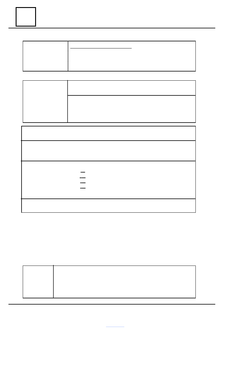
DF 060
PRESENT
OR
MEMORIZED
IDLING ADJUSTMENT CIRCUIT
1.DEF : Open circuit or short-circuit
CO : Open circuit
CC.O : Short-circuit at mass
CC.1 : Short-circuit at +12 volts
Check the connection and condition of the step-by-step engine connector for idling adjustment
Replace the connector if necessary.
Check the resistance of the step-by-step engine for idling adjustment. Refer to chapter “Help” in
order to compare the measured resistance values with the recommended ones.
Replace the step-by-step engine valves if necessary.
Check the insulation, continuity and absence of the parasite resistance on lines:
Pin 12 injection computer > pin B step-by-step engine for idling adjustment
Pin 41 injection computer > pin A step-by-step engine for idling adjustment
Pin 42 injection computer > pin C step-by-step engine for idling adjustment
Pin 72 injection computer > pin D step-by-step engine for idling adjustment
Fix if necessary.
If the problem is persisting after these checking, treat the other failures then perform the conformity
checking.
Diagnostic – Failures interpretation