Dacia Solenza (engine E7J). Manual - part 25
IGNITION AND INJECTION
17
17 - 6
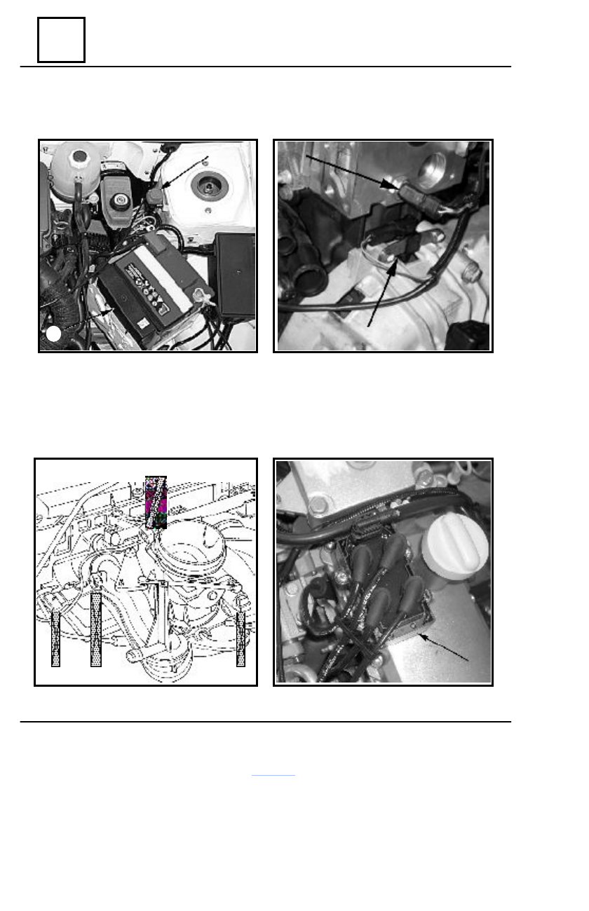
7.
UCE injection;
8. Choke sensor;
1.
RPM sensor
;
2.
Water temperature sensor
;
Injection system
8
7
2
1
4
5
6
3
3.
Atmospheric pressure sensor
;
4.
Step-by-step engin e for idli ng
adjustment
;
5.
Valve position potentiometer
;
6.
Air temperature sensor;
;
13.
Ignition coil
;
13