Dacia Solenza (engine E7J). Manual - part 13


  Index      Dacia     Dacia Solenza (engine E7J) - service repair manual 2004 year


Search            


Content   ..  11  12  13  14   ..


Dacia Solenza (engine E7J). Manual - part 13


ENGINE

 E7J-262

10

ENGINE ASSEMBLY

10 - 27

CYLINDERS BLOCK DISMOUNTING

Dismount:

- water inlet pipe and oil dipper rod

guide ( their sealing is performed by means of
rubber rings that must be replaced at each dis-
mounting);

- clutch;
- engine flywheel, immobilized by means

of the MOT 582;

- lower crankcase;
- crankshaft gear;
- tightening roller;
- crankshaft closing casing;

Dismounting – Remounting

-

water pump.

Dismount the oil pump attachment screws.
Dismount the oil pump and its driving chain.
Mark the connecting rod caps compared

with the connecting rod  body.

ATTENTION!

   Do not use punches for marking in or-
der to avoid cracks occurring; a perma-
nent marker is to be used.

Dismount
- connecting rods caps and the bearings;
- jackets maintaining device MOT 484 or

clamps MOT 588;

- assembly jackets-pistons-connecting

rods;

- bearings caps and their bearings;
- crankshaft and axial clearance bearings;
- bearings from the cylinders block.
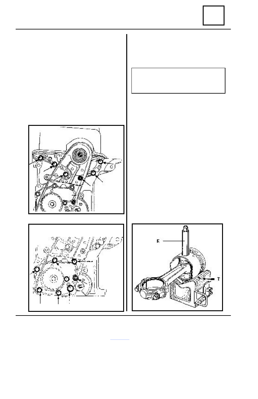
 PISTONS SHAFTS DI

SMOUNTING

Place the piston on  the  support lining up

the piston bolt (shaft) with the gap whole from
the support (two T lines for marking  the  whole
center are facilitating the lining up).

Remove the bolts using a press by means

of the extraction mandrel E.

ENGINE  E7J-262

10

ENGINE ASSEMBLY

10 - 28

CYLINDERS BLOCK 

REMOUNTING

Clean the cylinders block, especially the

jackets seating and sealing surfaces.

Preparation of assembly
    “ pistons-jackets”

The parts contained in the kit are in pairs.
Mark the parts assembly from  A to D in

order to keep the matching.

Dismounting – Remounting

Remove completely the anti-rust foil.

REMARK:
Never scrape the parts.

Jackets over-height

These engines are equipped with rubber

rings for jackets sealing, ensuring only the seal-
ing, jackets being seated directly on the cylin-
ders block and over-height being done from
manufacturing.

The checking of the jackets over-height is

to be performed as follows:

- place the jackets in the cylinders block

without the sealing ring;

- check the X over-height by means of

the devices MOT 251-01 and MOT 252-01.

ENGINE

 E7J-262

10

ENGINE ASSEMBLY

10 - 29

Dismounting – Remounting

 The over-height X must be between 0.02

mm and 0.09 mm.

Place the jackets  in such way that :

- the difference between two joint jackets

to be maximum 0.05 mm;

- the over-height to be in ascending order

between cylinders 1 and 4;

- in case of an incorrect over-height, check

the over-height by means of a new kit of jack-
ets, in order to see if the cause is the block or
the cylinders jacket or check the theoretical size
values of the block and of the jackets.

When over-height is correctly obtained, per-

form the  A, B, C, D assembly then mark  with
numbers jackets, pistons and the bolts from 1
to (no.1 towards flywheel) so that the  corre-
spondence with the corresponding connecting
rods may be achieved.

Pistons bolts mounting

The pistons bolts are fixed in connecting rods

and free in pistons.

Mount the pistons bolts by means of the

MOT 574-22 that is containing:

- a support for piston (S);
- an extracting mandrel (M);
- the piston supporting bushings (B);
- the bolts for mounting (A) provided with

their centering guides (C).

Use an electric plate  of 1500 W (electric

oven) for  connecting rods heating.

Place the connecting rods on the electric

plate so that connecting rod  end  surfaces are
in contact with the heating plate.

Check if the pistons bolts are freely gliding

in the new corresponding pistons.

Mount the piston bolt E on the mounting

bolt A.

Screw the centering guide C till end and

then unscrew it for a quarter of turn.

ENGINE  E7J-262

10

ENGINE ASSEMBLY

10 - 30

The arrow marked on the piston head must

be oriented towards engine flywheel.

The connecting rods have no  mounting

direction, but the half-bearings spurs are to
be positioned on the same part.

In order to assemble the piston and the

connecting rod,  proceed as follows:

- place the bushing B 13 on the support

and attach the piston (with the arrow oriented
upwards) on the bushing;

Dismounting – Remounting

- lubricate the centering  guide and  the

piston bolt with engine oil;

- check the free gliding of the piston

bolt and the piston positioning.

When the connecting rod end is reaching

the necessary temperature (about  250 °C),
proceed to the rapid of the piston bolt, as
follows:

- introduce the centering guide in the

piston;

- position the connecting rod in the

piston;

- press till end  the piston bold.

Check if the piston bolt is remaining re-

tired as against the piston outer diameter for
each of the connecting rod position in the pis-
ton.

Rings mounting
Mount the rings  on the piston in the

following sequence:

- oiling ring (3);
- sealing ring  (2) with the mark  “TOP

upwards;

- compression ring (1) with the mark

TOP” upward.

The compression and sealing rings are to be

mounted with the slots disposed at 90° against
de bolt’s axle and displaced between them with
180°. The oiling ring is to be mounted with the
slot oriented at  45°  against the bolt’s axle.

The rings slots being adjusted, shall never be

reworked.

Lubricate the  pistons with engine oil.
Mount the assemblies “connecting rod-

piston-rings” in the cylinder’s jackets, by means
of the mounting bushing.

Mount the sealing gaskets on the cylinder

jackets.


Content   ..  11  12  13  14   ..