содержание .. 41 42 43 44 ..
Peugeot 405. Manual - part 43
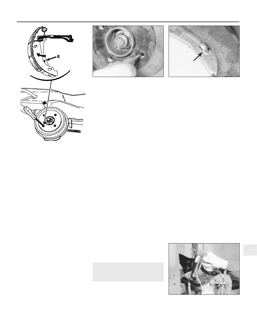
that it contacts the handbrake operating
lever on the trailing brake shoe. Push the
lever until the stop-peg slips behind the
brake shoe web, allowing the brake shoes
to retract fully (see illustrations). The
brake drum can now be withdrawn.
Inspection
Note: If either drum requires renewal, BOTH
should be renewed at the same time, to
ensure even and consistent braking. New
brake shoes should also be fitted.
4 Working carefully, remove all traces of
brake dust from the drum, but avoid inhaling
the dust, as it is injurious to health.
5 Clean the outside of the drum, and check it
for obvious signs of wear or damage, such as
cracks around the roadwheel bolt holes;
renew the drum if necessary.
6 Examine carefully the inside of the drum.
Light scoring of the friction surface is normal,
but if heavy scoring is found, the drum must
be renewed. It is usual to find a lip on the
drum’s inboard edge which consists of a
mixture of rust and brake dust; this should be
scraped away, to leave a smooth surface
which can be polished with fine (120- to 150-
grade) emery paper. If, however, the lip is due
to the friction surface being recessed by
excessive wear, then the drum must be
renewed.
7 If the drum is thought to be excessively
worn, or oval, its internal diameter must be
measured at several points using an internal
micrometer. Take measurements in pairs, the
second at right-angles to the first, and
compare the two, to check for signs of ovality.
Provided that it does not enlarge the drum to
beyond the specified maximum diameter, it
may be possible to have the drum refinished
by skimming or grinding; if this is not possible,
the drums on both sides must be renewed.
Note that if the drum is to be skimmed, BOTH
drums must be refinished, to maintain a
consistent internal diameter on both sides.
Refitting
8 If a new brake drum is to be installed, use a
suitable solvent to remove any preservative
coating that may have been applied to its
interior. Note that it may also be necessary to
shorten the adjuster strut length, by rotating
the strut wheel, to allow the drum to pass over
the brake shoes.
9 Ensure that the handbrake lever stop-peg is
correctly repositioned against the edge of the
brake shoe web (see illustration), and ensure
that the mating faces of the hub and brake
drum are clean, then slide the brake drum
onto the hub.
10 Refit and tighten the drum retaining
screw.
11 Depress the footbrake several times to
operate the self-adjusting mechanism.
12 Repeat the above procedure on the
remaining rear brake assembly (where
necessary), then check and, if necessary,
adjust the handbrake cable as described in
Section 17.
13 On completion, refit the roadwheel(s),
then lower the vehicle to the ground and
tighten the wheel bolts to the specified
torque.
10 Front brake caliper - removal,
overhaul and refitting
3
Note: Before starting work, refer to the note at
the beginning of Section 2 concerning the
dangers of hydraulic fluid, and to the warning
at the beginning of Section 4 concerning the
dangers of asbestos dust.
Bendix caliper
Removal
1 Apply the handbrake, then jack up the front
of the vehicle and support it on axle stands
(see “Jacking and Vehicle Support”). Remove
the appropriate roadwheel.
2 Minimise fluid loss by first removing the
master cylinder reservoir cap, and then
tightening it down onto a piece of polythene,
to obtain an airtight seal. Alternatively, use a
brake hose clamp, a G-clamp or a similar tool
to clamp the flexible hose (see illustration).
3 Remove the brake pads as described in
Section 4.
4 Clean the area around the union, then
loosen the fluid hose union nut.
5 Slacken the two bolts securing the caliper
assembly to the hub carrier and remove them
along with the mounting plate, noting which
way around the plate is fitted. Lift the caliper
assembly away from the brake disc, and
unscrew it from the end of the fluid hose. Plug
the open ends of the caliper and hose to
prevent dirt ingress and fluid loss.
Overhaul
6 The caliper can be overhauled after
obtaining the relevant repair kit from a
Peugeot dealer. Ensure that the correct repair
kit is obtained for the caliper being worked on.
Note the locations of all components to
ensure correct refitting, and lubricate the new
seals using clean brake fluid. Follow the
assembly instructions supplied with the repair
kit (see illustration).
Braking system 9•11
9.9 Check that the handbrake lever stop-
peg (arrowed) is against the shoe edge
E Handbrake operating lever stop-peg location
10.2 Using a clamp on the caliper
hydraulic hose
9.3b Releasing the handbrake
operating lever
9
9.3a Using a screwdriver inserted through
the brake drum to release the handbrake
operating lever