содержание .. 33 34 35 36 ..
Peugeot 405. Manual - part 35
6 Connect an exhaust gas analyser to the
vehicle in accordance with the manufacturer’s
instructions.
7 Start the engine and allow it to idle. Turn
the mixture adjustment screw in or out to
obtain the specified CO content (see
illustration).
8 Re-adjust the idle speed as previously
described.
9 On completion, stop the engine, remove all
test equipment and fit a new tamperproof cap
to the screw.
Bosch ML4.1 system
10 The idle speed is non-adjustable. It is
controlled by the idle speed regulator valve.
11 To check the mixture (CO), first ensure
that the conditions in paragraph 3 are met.
12 Connect an exhaust gas analyser to the
vehicle in accordance with the manufacturer’s
instructions.
13 Remove the tamperproof cap from the
mixture adjustment screw on the airflow meter
housing.
14 Turn the screw clockwise to increase and
anti-clockwise to decrease CO content until
the specified CO level is obtained.
15 Remove all test equipment and fit a new
tamperproof plug to the screw.
Bosch LU2-Jetronic system
16 Idle speed is adjusted as described for
the Bosch L3.1 system (see illustration).
17 Idle mixture is not adjustable, and is
automatically regulated by the electronic
control unit according to signals provided by
the oxygen sensor.
Bosch Motronic M1.3 system
18 Idle speed is only adjustable on 8-valve
engines; on 16-valve engines it is controlled
by the ECU. On 8-valve engines use the
procedure given in paragraphs 3 and 4.
19 Adjustment of idle mixture is as given in
paragraphs 5 to 9.
MM8P, Sagem-Lucas 4GJ,
Bosch Motronic 5.1,
Bosch Motronic 3.2 systems
20 Experienced home mechanics with a
considerable amount of skill and equipment
(including a tachometer and an accurately
calibrated exhaust gas analyser) may be able
to check the exhaust CO level and the idle
speed. However, if these are found to be in
need of adjustment, the car must be taken to
a suitably-equipped Peugeot dealer for further
testing. Neither the mixture adjustment
(exhaust gas CO level) nor the idle speed are
adjustable, and should either be incorrect, a
fault must be present in the fuel injection
system.
12 Throttle housing -
removal and refitting
2
Note: At the time or writing no information
was available for the Sagem-Lucas system.
Removal
1 Disconnect the battery negative terminal.
Bosch Jetronic system
2 Remove the airflow meter with reference to
Section 2.
3 Disconnect the accelerator cable from the
throttle housing.
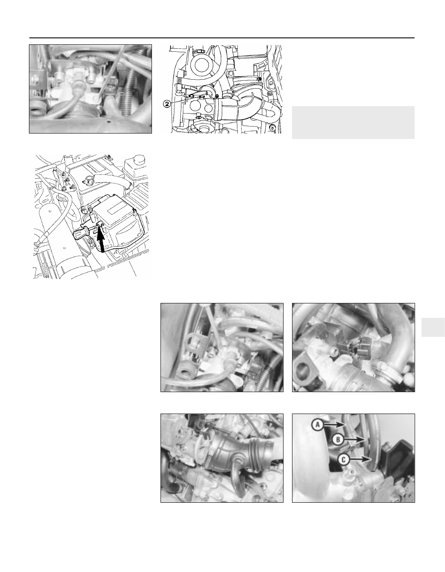
4 Either drain the cooling system or clamp
the coolant hoses as close as possible to the
throttle housing, then disconnect the coolant
inlet hose (see illustration).
5 Disconnect the throttle switch wiring multi-
plug (see illustration).
6 Loosen the clip and detach the plastic duct
from the throttle housing (see illustration).
7 Disconnect the coolant return hose,
distributor vacuum hose and breather hose
from the throttle housing (see illustration).
Fuel/exhaust systems - multi-point fuel injection models 4C•5
11.16 Idle speed adjustment screw (2)
(LU2-Jetronic system)
12.7 Disconnect the coolant return (A),
distributor vacuum hose (B)
and breather hose (C)
12.6 Detach the plastic duct
12.5 Disconnecting the multi-plug
12.4 Disconnecting the coolant inlet hose
4C
11.4 Adjusting the idle speed screw on the
Bosch L3.1 system
11.7 Mixture (CO ) adjustment screw on
the airflow meter (Bosch L3.1 system)