Peugeot 405. Manual - part 20


  Главная      Peugeot     Peugeot 405 (1988-1997) - Service And Repair Manual Haynes


поиск по сайту            


содержание   ..  18  19  20  21   ..


Peugeot 405. Manual - part 20


sprocket, fitted to the crankshaft, be renewed
at the same time. To renew the chain and
drive sprocket, first remove the crankshaft
timing belt sprocket as described in Section 8.
Unbolt the oil seal carrier from the cylinder
block. The sprocket and chain can then be
slid off the end of the crankshaft. Refer to Part
C for further information.
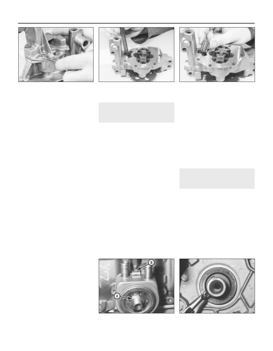
Slacken and remove the bolts (along with
the baffle plate, where fitted) securing the
strainer cover to the pump body. Lift off the
strainer cover, and take off the relief valve
piston and spring, noting which way round
they are fitted (see illustrations).
Examine the pump rotors and body for
signs of wear ridges or scoring. If worn, the
complete pump assembly must be renewed.
Examine the relief valve piston for signs of
wear or damage, and renew if necessary. The
condition of the relief valve spring can only be
measured by comparing it with a new one; if
there is any doubt about its condition, it
should also be renewed. Both the piston and
spring are available individually.
Thoroughly clean the oil pump strainer with
a suitable solvent, and check it for signs of
clogging or splitting. If the strainer is
damaged, the strainer and cover assembly
must be renewed.
Locate the relief valve spring and piston in
the strainer cover. Refit the cover to the pump
body, aligning the relief valve piston with its
bore in the pump. Refit the baffle plate (where
fitted) and the cover retaining bolts, and
tighten them securely.

Refitting

10 Offer up the spacer plate (where fitted),
then locate the pump sprocket with its drive
chain. Seat the pump on the base of the
cylinder block/crankcase. Refit the pump
retaining bolts, and tighten them to the
specified torque setting.
11 Where necessary, slide the sprocket
cover into position on the pump. Refit its
retaining bolts, tightening them securely.
12 Refit the sump as described in Section 13.

15 Oil cooler -

removal and refitting

2

Note: The oil cooler is not fitted to all models.

Removal

Firmly apply the handbrake, then jack up
the front of the vehicle and support it on axle
stands (see “Jacking and Vehicle Support”).
Drain the cooling system as described in
Chapter 1. Alternatively, clamp the oil cooler
coolant hoses directly above the cooler, and
be prepared for some coolant loss as the
hoses are disconnected.
Position a suitable container beneath the oil
filter. Unscrew the filter using an oil filter
removal tool if necessary, and drain the oil
into the container. If the oil filter is damaged or
distorted during removal, it must be renewed.
Given the low cost of a new oil filter relative to
the cost of repairing the damage which could
result if a re-used filter springs a leak, it is
probably a good idea to renew the filter in any
case.
Release the hose clips, and disconnect the
coolant hoses from the oil cooler.
Unscrew the oil cooler/oil filter mounting
bolt from the cylinder block, and withdraw the
cooler. Note the locating notch in the cooler
flange, which fits over the lug on the cylinder
block (see illustration). Discard the oil cooler
sealing ring; a new one must be used on
refitting.

Refitting

Fit a new sealing ring to the recess in the
rear of the cooler, then offer the cooler to the
cylinder block.
Ensure that the locating notch in the cooler
flange is correctly engaged with the lug on the
cylinder block, then refit the mounting bolt
and tighten it securely.
Fit the oil filter, then lower the vehicle to the
ground. Top-up the engine oil (refer to
“Weekly Checks”).
Refill or top-up the cooling system (as
applicable) -see Chapter 1. Start the engine,
and check the oil cooler for signs of leakage.

16 Crankshaft oil seals - renewal

4

Right-hand oil seal

Remove the crankshaft sprocket and
flanged spacer as described in Section 8.
Secure the timing belt clear of the working
area, so that it cannot be contaminated with
oil. Make a note of the correct fitted depth of
the seal in its housing.
Punch or drill two small holes opposite each
other in the seal. Screw a self-tapping screw
into each, and pull on the screws with pliers to
extract the seal (see illustration). The seal can
also be levered out. Use a flat-bladed
screwdriver, but take care not to damage the
crankshaft shoulder or seal housing.

2B•22 XU engine in-car repair procedures

14.5a  Remove the oil pump cover

retaining bolts . . .

14.5c  . . . and relief valve piston, noting

which way round it is fitted

16.2  Using a self-tapping screw and pliers

to remove the crankshaft oil seal

15.5  Oil cooler/oil filter mounting bolt (A)

and locating notch (B)

14.5b  . . . then lift off the cover and

remove the spring . . .

Clean the seal housing, and be sure to
polish off any burrs or raised edges, which
may have caused the seal to fail in the first
place.
Lubricate the lips of the new seal with clean
engine oil, and carefully locate the seal on the
end of crankshaft. Note that its sealing lip
must be facing inwards. Take care not to
damage the seal lips during fitting.
Fit the new seal using a suitable tubular
drift, such as a socket, which bears only on
the hard outer edge of the seal. Tap the seal
into position, to the same depth in the housing
as the original was prior to removal.
Wash off any traces of oil, then refit the
crankshaft sprocket as described in 
Section 8.

Left-hand oil seal

Remove the flywheel/driveplate as
described in Section 17. Make a note of the
correct fitted depth of the seal in its housing.
Punch or drill two small holes opposite
each other in the seal. Screw a self-tapping
screw into each, and pull on the screws with
pliers to extract the seal.
Clean the seal housing, and polish off any
burrs or raised edges, which may have
caused the seal to fail in the first place.
10 Lubricate the lips of the new seal with
clean engine oil, and carefully locate the seal
on the end of the crankshaft.
11 Fit the new seal using a suitable tubular
drift, which bears only on the hard outer edge
of the seal. Drive the seal into position, to the
same depth in the housing as the original was
prior to removal.
12 Wash off any traces of oil, then refit the
flywheel/driveplate with reference to 
Section 17.

17 Flywheel/driveplate -

removal, inspection and
refitting

4

Removal

Flywheel - 
models with manual transmission

Remove the transmission as described in
Chapter 7A, then remove the clutch assembly
as described in Chapter 6.
Prevent the flywheel from turning by locking
the ring gear teeth with a similar arrangement
to that shown in illustration 5.3 (Section 5).
Alternatively, bolt a strap between the
flywheel and the cylinder block/crankcase. Do
not 
attempt to lock the flywheel in position
using the crankshaft pulley locking pin
described in Section 3.
Slacken and remove the flywheel retaining
bolts, and remove the flywheel from the end
of the crankshaft. Be careful not to drop it; it is
heavy. If the flywheel locating dowel is a loose
fit in the crankshaft end, remove it and store it
with the flywheel for safe-keeping. Discard the

flywheel bolts; new ones must be used on
refitting.

Driveplate - 
models with automatic transmission

Remove the transmission as described in
Chapter 7B. Lock the driveplate as described
in paragraph 2. Mark the relationship between
the torque converter plate and the driveplate,
and slacken all the driveplate retaining bolts.
Remove the retaining bolts, along with the
torque converter plate and the two shims (one
fitted on each side of the torque converter
plate). Note that the shims are of different
thickness, the thicker one being on the
outside of the torque converter plate. Discard
the driveplate retaining bolts; new ones must
be used on refitting.
Remove the driveplate from the end of the
crankshaft. If the locating dowel is a loose fit
in the crankshaft end, remove it and store it
with the driveplate for safe-keeping.

Inspection

On models with manual transmission,
examine the flywheel for scoring of the clutch
face, and for wear or chipping of the ring gear
teeth. If the clutch face is scored, the flywheel
may be surface-ground, but renewal is
preferable. Seek the advice of a Peugeot
dealer or engine reconditioning specialist to
see if machining is possible. If the ring gear is
worn or damaged, the flywheel must be
renewed, as it is not possible to renew the
ring gear separately.
On models with automatic transmission,
check the torque converter driveplate
carefully for signs of distortion. Look for any
hairline cracks around the bolt holes or
radiating outwards from the centre, and
inspect the ring gear teeth for signs of wear or
chipping. If any sign of wear or damage is
found, the driveplate must be renewed.

Refitting

Flywheel - 
models with manual transmission

Clean the mating surfaces of the flywheel
and crankshaft. Remove any locking
compound from the threads of the crankshaft
holes, using the correct-size tap, if available.

10 If the new flywheel retaining bolts are not
supplied with their threads already pre-
coated, apply a suitable thread-locking
compound to the threads of each bolt (see
illustration)
.
11 Ensure that the locating dowel is in
position. Offer up the flywheel, locating it on
the dowel, and fit the new retaining bolts.
12 Lock the flywheel using the method
employed on dismantling, and tighten the
retaining bolts to the specified torque (see
illustration)
.
13 Refit the clutch as described in Chapter 6.
Remove the flywheel locking tool, and refit the
transmission as described in Chapter 7A.

Driveplate - 
models with automatic transmission

14 Carry out the operations described above
in paragraphs 9 and 10, substituting
“driveplate” for all references to the flywheel.
15 Locate the driveplate on its locating
dowel.
16 Offer up the torque converter plate, with
the thinner shim positioned behind the plate
and the thicker shim on the outside, and align
the marks made prior to removal.
17 Fit the new retaining bolts, then lock the
driveplate using the method employed on
dismantling. Tighten the retaining bolts to the
specified torque wrench setting.
18 Remove the driveplate locking tool, and
refit the transmission (see Chapter 7B).

18 Engine/transmission

mountings - inspection and
renewal

2

Inspection

If improved access is required, raise the
front of the car and support it securely on axle
stands (see “Jacking and Vehicle Support”).

XU engine in-car repair procedures  2B•23

17.12  . . . then refit the flywheel, and

tighten the bolts to the specified torque

17.10  If the new flywheel bolt threads are

not supplied with their threads pre-coated,

apply locking compound to them . . .

2B

If a suitable tap is not
available, cut two slots
along the threads of one of
the old flywheel bolts, and

use the bolt to remove the locking
compound from the threads.

Check the mounting rubber to see if it is
cracked, hardened or separated from the
metal at any point; renew the mounting if any
such damage or deterioration is evident.
Check that all the mounting’s fasteners are
securely tightened; use a torque wrench to
check if possible.
Using a large screwdriver or a crowbar,
check for wear in the mounting by carefully
levering against it to check for free play.
Where this is not possible, enlist the aid of an
assistant to move the engine/transmission
back and forth, or from side to side, while you
watch the mounting. While some free play is
to be expected even from new components,
excessive wear should be obvious. If
excessive free play is found, check first that
the fasteners are correctly secured, then
renew any worn components as described
below.

Renewal

Right-hand mounting - 1580 cc, 
1761 cc and 1905 cc models

Disconnect the battery negative lead.
Release all the relevant hoses and wiring from
their retaining clips, and position clear of the
mounting so that they do not hinder the
removal procedure.
Place a jack beneath the engine, with a
block of wood on the jack head. Raise the
jack until it is supporting the weight of the
engine.
Slacken and remove the three nuts
securing the right-hand mounting bracket to
the engine. Remove the single nut securing
the bracket to the mounting rubber, and lift off
the bracket.
Lift the rubber buffer plate off the mounting
rubber stud, then unscrew the mounting
rubber from the body and remove it from the
vehicle. If necessary, the mounting bracket
can be unbolted and removed from the side of
the cylinder head.
Check all components carefully for wear or
damage, and renew them where necessary.
10 On reassembly, screw the mounting
rubber into the vehicle body, and tighten it
securely. Where removed, refit the mounting

bracket to the side of the cylinder head, and
securely tighten its retaining bolts.
11 Refit the rubber buffer plate to the
mounting rubber stud, and install the
mounting bracket.
12 Tighten the mounting bracket retaining
nuts to the specified torque setting.
13 Remove the jack from underneath the
engine, and reconnect the battery negative
terminal.

Right-hand mounting - 
1998 cc 8-valve and 16-valve models

14 Disconnect the battery negative lead.
Release all the relevant hoses and wiring from
their retaining clips. Place the hoses/wiring
clear of the mounting so that the removal
procedure is not hindered.
15 Place a jack beneath the engine, with a
block of wood on the jack head. Raise the
jack until it is supporting the weight of the
engine.
16 Undo the two bolts securing the curved
mounting retaining plate to the body. Lift off
the plate, and withdraw the rubber damper
from the top of the mounting bracket.
17 Slacken and remove the two nuts and two
bolts securing the right-hand engine/
transmission mounting bracket to the engine.
Remove the single nut securing the bracket to
the mounting rubber, and lift off the bracket.
18 Lift the rubber buffer plate off the
mounting rubber stud, then unscrew the
mounting rubber from the body and remove it
from the vehicle. If necessary, the mounting
bracket can be unbolted and removed from
the front of the cylinder block.
19 Check all components carefully for signs
of wear or damage, and renew as necessary.
20 On reassembly, screw the mounting
rubber into the vehicle body, and tighten it
securely. Where removed, refit the mounting
bracket to the front of the cylinder block, and
securely tighten its retaining bolts.
21 Refit the rubber buffer plate to the
mounting rubber stud, and install the
mounting bracket.
22 Tighten the mounting bracket retaining
nuts to the specified torque setting, and
remove the jack from underneath the engine.

23 Refit the rubber damper to the top of the
mounting bracket, and refit the curved
retaining plate. Tighten the retaining plate
bolts to the specified torque, and reconnect
the battery.

Left-hand mounting

24 Remove the battery and battery tray, as
described in Chapter 5. Slacken and remove
the battery support plate mounting bolts.
Release the wiring from its retaining clip on
the plate, and remove the plate from the
engine compartment.
25 Place a jack beneath the transmission,
with a block of wood on the jack head. Raise
the jack until it is supporting the weight of the
transmission.
26 Slacken and remove the centre nut and
washer from the left-hand mounting. Undo the
two bolts securing the mounting bracket
assembly to the vehicle body, and remove the
assembly from the mounting stud.
27 Slide the spacer off the mounting stud,
then unscrew the stud from the top of the
transmission housing, and remove it along
with its washer. If the mounting stud is tight, a
universal stud extractor can be used to
unscrew it.
28 Check all components carefully for signs
of wear or damage, and renew as necessary.
29 Clean the threads of the mounting stud,
and apply a coat of thread-locking compound
to its threads. Refit the stud and washer to the
top of the transmission, and tighten it to the
specified torque setting.
30 Slide the spacer onto the mounting stud,
then refit the mounting bracket assembly.
Tighten both the mounting bracket-to-body
bolts and the mounting centre nut to their
specified torque settings, and remove the jack
from underneath the transmission.
31 Refit the battery support plate, tightening
its retaining bolts securely, then refit the
battery as described in Chapter 5.

Rear mounting

32 Refer to Part A of this Chapter, 
Section 16.

2B•24 XU engine in-car repair procedures

2C

NoteAt the time of writing, many specifications for the 1761 cc and 1998 cc (16-valve) engines were not available. Where the relevant specifica-
tions are not given here, refer to your Peugeot dealer for further information.

Cylinder head

Maximum gasket face distortion  . . . . . . . . . . . . . . . . . . . . . . . . . . . . . .

0.05 mm

Cylinder head height:

Standard:

1360 cc engines  . . . . . . . . . . . . . . . . . . . . . . . . . . . . . . . . . . . . . . .

111.2 ± 0.08 mm

1580 cc, 1761 cc, 1905 cc (8-valve) and 
1998 cc  (8-valve and 16-valve) engines . . . . . . . . . . . . . . . . . . . . .

158.93 ± 0.05 mm

1905 cc (16-valve) engines  . . . . . . . . . . . . . . . . . . . . . . . . . . . . . . .

132.0 ± 0.15 mm

Minimum after refinishing:

1360 cc engines  . . . . . . . . . . . . . . . . . . . . . . . . . . . . . . . . . . . . . . .

111.0 mm

1580 cc, 1761 cc, 1905 cc (8-valve) and 
1998 cc (8-valve and 16-valve) engines  . . . . . . . . . . . . . . . . . . . . .

158.73 mm

1905 cc (16-valve) engines  . . . . . . . . . . . . . . . . . . . . . . . . . . . . . . .

131.8 mm

Valves

Valve head diameter:

Inlet:

1360 cc engines  . . . . . . . . . . . . . . . . . . . . . . . . . . . . . . . . . . . . . . .

36.8 mm

1580 cc engine  . . . . . . . . . . . . . . . . . . . . . . . . . . . . . . . . . . . . . . . .

41.6 mm

1761 cc engine  . . . . . . . . . . . . . . . . . . . . . . . . . . . . . . . . . . . . . . . .

Not available

1905 cc 8-valve engine  . . . . . . . . . . . . . . . . . . . . . . . . . . . . . . . . . .

41.8 mm

1998 cc 8-valve engine  . . . . . . . . . . . . . . . . . . . . . . . . . . . . . . . . . .

42.6 mm

1905 cc and 1998 cc 16-valve engines  . . . . . . . . . . . . . . . . . . . . .

34.7 mm

Exhaust:

1360 cc engines  . . . . . . . . . . . . . . . . . . . . . . . . . . . . . . . . . . . . . . .

29.4 mm

1580 cc and 1905 cc (8-valve) engines  . . . . . . . . . . . . . . . . . . . . .

34.7 mm

1761 cc engine  . . . . . . . . . . . . . . . . . . . . . . . . . . . . . . . . . . . . . . . .

Not available

1998 cc 8-valve engine  . . . . . . . . . . . . . . . . . . . . . . . . . . . . . . . . . .

34.5 mm

1905 cc and 1998 cc 16-valve engines  . . . . . . . . . . . . . . . . . . . . .

29.7 mm

Chapter 2  Part C:
Engine removal and overhaul procedures

Crankshaft - inspection  . . . . . . . . . . . . . . . . . . . . . . . . . . . . . . . . . . .14
Crankshaft - refitting and main bearing running clearance check  . . .18
Crankshaft - removal  . . . . . . . . . . . . . . . . . . . . . . . . . . . . . . . . . . . . .11
Cylinder block/crankcase - cleaning and inspection  . . . . . . . . . . . . .12
Cylinder head - dismantling  . . . . . . . . . . . . . . . . . . . . . . . . . . . . . . . . .7
Cylinder head - reassembly  . . . . . . . . . . . . . . . . . . . . . . . . . . . . . . . . .9
Cylinder head and valves - cleaning and inspection  . . . . . . . . . . . . . .8
Engine - initial start-up after overhaul  . . . . . . . . . . . . . . . . . . . . . . . .20
Engine and automatic transmission - 

removal, separation and refitting  . . . . . . . . . . . . . . . . . . . . . . . . . . .5

Engine and manual transmission - removal, separation and refitting  . . .4

Engine overhaul - dismantling sequence  . . . . . . . . . . . . . . . . . . . . . . .6
Engine overhaul - general information  . . . . . . . . . . . . . . . . . . . . . . . . .2
Engine overhaul - reassembly sequence  . . . . . . . . . . . . . . . . . . . . . .16
Engine/transmission removal - methods and precautions  . . . . . . . . . .3
General information  . . . . . . . . . . . . . . . . . . . . . . . . . . . . . . . . . . . . . . .1
Main and big-end bearings - inspection . . . . . . . . . . . . . . . . . . . . . . .15
Piston rings - refitting  . . . . . . . . . . . . . . . . . . . . . . . . . . . . . . . . . . . . .17
Piston/connecting rod assembly - inspection  . . . . . . . . . . . . . . . . . .13
Piston/connecting rod assembly - 

refitting and big-end bearing running clearance check  . . . . . . . . .19

Piston/connecting rod assembly - removal  . . . . . . . . . . . . . . . . . . . .10

2C•1

Easy, suitable for
novice with little
experience

Fairly easy, suitable
for beginner with
some experience

Fairly difficult,
suitable for competent
DIY mechanic

Difficult, suitable for
experienced  DIY
mechanic

Very difficult,
suitable for expert
DIY or  professional

Degrees of difficulty

Specifications

Contents


содержание   ..  18  19  20  21   ..