Opel Frontera UE. Manual - part 561


  Index      Opel     Opel Frontera UE - service repair manual 1999-2001 year


Search            


Content   ..  559  560  561  562   ..


Opel Frontera UE. Manual - part 561


8H–16

SECURITY AND LOCKS

Key

Key Coding

730RX001

Legend

EndOFCallout

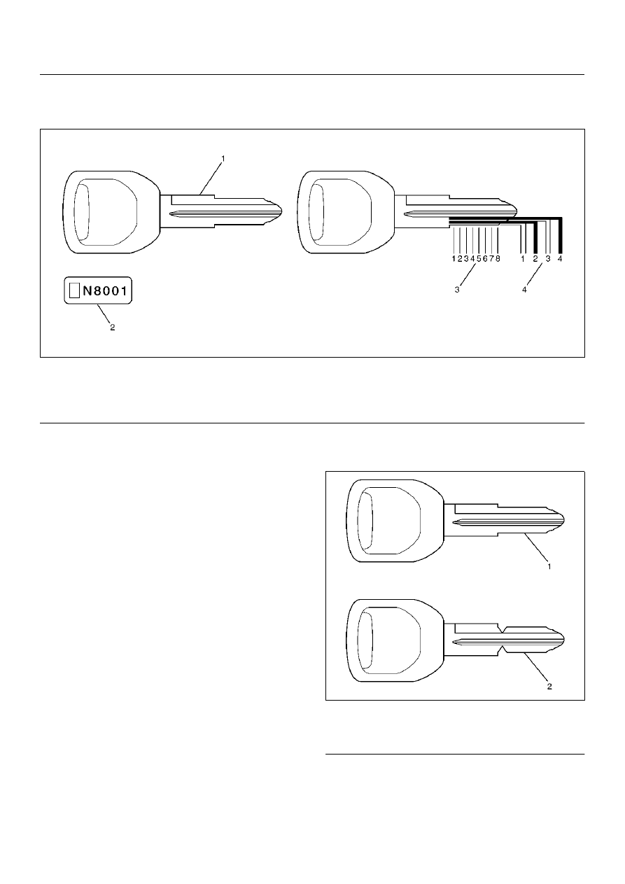
One key is used for the ignition, door, and tailgate lock 
cylinders. The keys are cut on both edges to make them 
reversible.
Key identification is obtained from the five character key 
code stamped on the key code tag. From this key code, 
the key code cutting combination can be determined 
from a code list (available to owners of key cutting 
equipment from suppliers).
If key codes are not available from records or tags, the 
key code can be obtained from the right hand door lock 
cylinder (if lock has not been replaced). Lock cylinders 
supplied by the factory as service parts are unmarked.
If the original key is available, the key code cutting 
combination can be determined by laying the key on the 
diagram shown in the figure.

Key Styles

730RX002

Legend

EndOFCallout

The keys come in styles A or B depending on the key 
code cutting combination. When the first position in the 
combination is a 1, 2 or 3, Style A is used. When the 
first position is a 4, Style B (factory pre-cut key) is used.

(1) Key (Actual size)
(2) Key Code Tag

(3) Position
(4) Level

(1) Blank Key Style “A"
(2) Blank Key Style “B"

SECURITY AND LOCKS

8H–17

Power Door Lock System

General Description

The circuit consists of the door lock (& power window) 
switch, door lock actuator for the front and rear door, 
tailgate lock actuator, fuel filler door lock actuator and 
the door lock key switch.
The front door lock switch–LH is always provided with 
the battery voltage.
The key or the inside lock button on the both driver's 
and the front passenger's door can activate the lock 
mechanism of all the doors (including the tailgate).
When the driver's door lock switch or the front 
passenger's door lock switch is turned on, current flows 
for about one second to the door lock actuator of each 
door connected in parallel with the front door lock (& 
power window) switch–LH to activate the actuator to 
lock and unlock the doors.

Door Lock Key Switch

Removal and Installation

• Refer to Front Door Lock Assembly in this section.

Front Door Lock Actuator

Removal and Installation

• Refer to Front Door Lock Assembly in this section.

Rear Door Lock Actuator

Removal and Installation

• Refer to Rear Door Lock Assembly in this section.

Tailgate Lock Actuator

Removal and Installation

• Refer to Tailgate Lock Assembly in this section.

Fuel Filler Door Lock Actuator

Removal and Installation

• Refer to Fuel Filler Door Lock in this section.

8H–18

SECURITY AND LOCKS

Keyless Entry System

General Description

This circuit consists of the keyless entry control unit, the 
front door lock & power window switch (RH), the starter 
switch, the dome light, the door switch and the tail gate 
switch and possible to be locked/unlocked each door by 
operation of transmitter. Basic function of system is as 
follows.

Keyless Entry Control Unit

Removal

1. Disconnect the battery ground cable.

2. Remove the instrument panel assembly (1).

• Refer to the Instrument Panel Assembly in Body 

Structure section.

3. Remove the keyless entry control unit (2).

• Disconnect the connector.

• Remove two fixing screws.

826RW007

Installation

To install, follow the removal steps in the reverse order.

Keyless Entry Control Unit/
Transmitter Replacement

Keyless Entry Control Unit Replacement

1. Remove and install the control unit.

• Refer to Keyless Entry Control Unit in this section.

2. Register ID code.

• Refer to ID Code Registration in Wiring System 

section.

3. Check that the keyless entry system works normally.

Transmitter Replacement

1. Prepare a new transmitter.

2. Regiter ID code.

• Refer to ID Code Registration in Wiring System 

section.

3. Check that the keyless entry system works normally.

Transmitter Battery Replacement

1. Remove a screw to remove the cover.

2. Remove the batteries.

3. Set the new batteries into the transmitter.

4. Install the cover to the transmitter.

5. Check that the keyless entry system works normally.

SECURITY AND LOCKS

8H–19

Main Data and Specifications

Torque Specifications

635RX008


Content   ..  559  560  561  562   ..