Nissan Frontier D40. Manual - part 856
MWI
POWER SUPPLY AND GROUND CIRCUIT
MWI-29
< COMPONENT DIAGNOSIS >
C
D
E
F
G
H
I
J
K
L
M
B
A
O
P
POWER SUPPLY AND GROUND CIRCUIT
COMBINATION METER
COMBINATION METER : Diagnosis Procedure
INFOID:0000000005275819
Regarding Wiring Diagram information, refer to
.
1.
CHECK FUSES
Check for blown combination meter fuses.
Is the inspection result normal?
YES
>> GO TO 2
NO
>> If fuse is blown, be sure to eliminate cause of malfunction before installing new fuse.
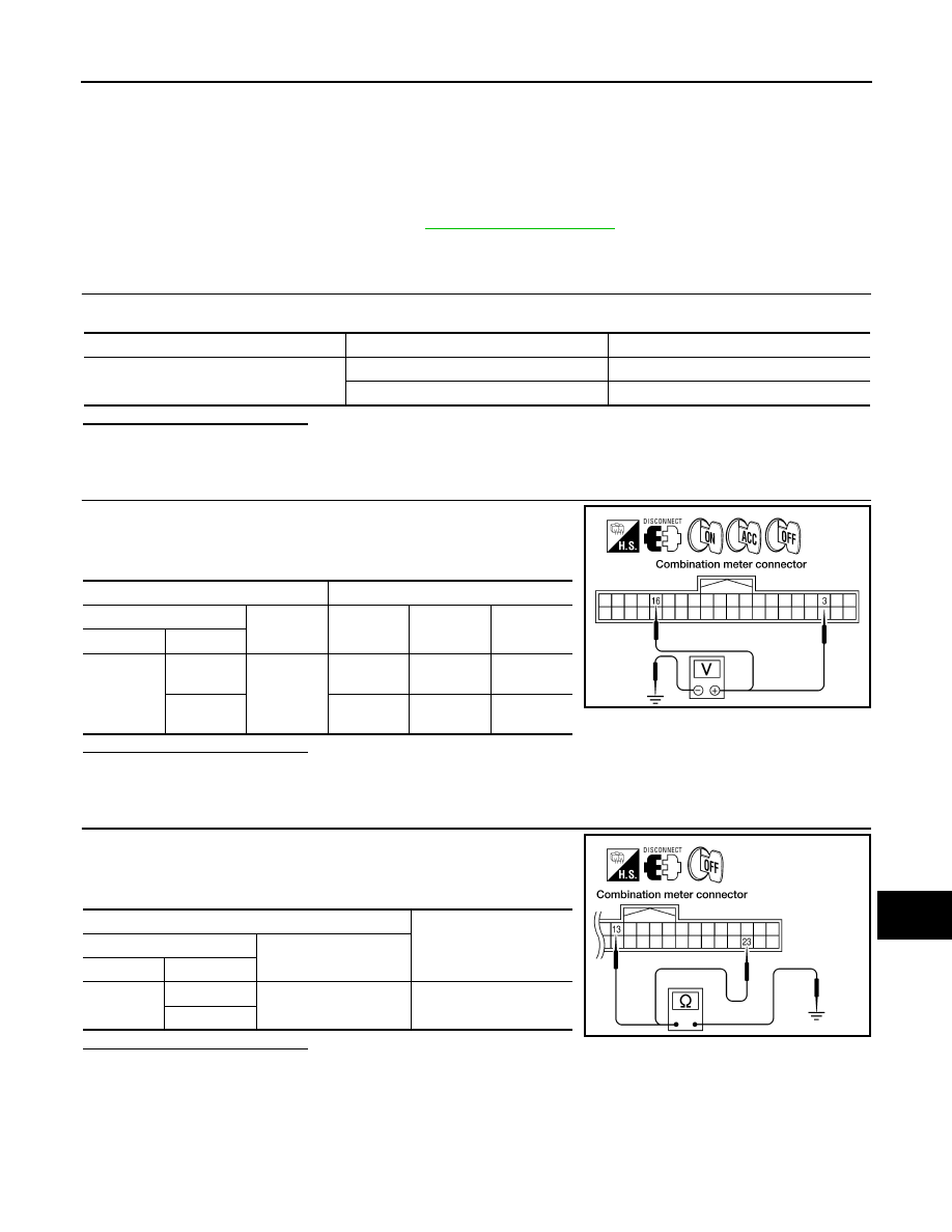
2.
POWER SUPPLY CIRCUIT CHECK
1.
Disconnect combination meter connector M24.
2.
Check voltage between combination meter harness connector
M24 terminals 3, 16 and ground.
Is the inspection result normal?
YES
>> GO TO 3
NO
>> Check harness for open between combination meter and fuse.
3.
GROUND CIRCUIT CHECK
1.
Turn ignition switch OFF.
2.
Check continuity between combination meter harness connector
M24 terminals 13, 23 and ground.
Is the inspection result normal?
YES
>> Inspection End.
NO
>> Check ground harness.
BCM (BODY CONTROL MODULE)
Unit
Power source
Fuse No.
Combination meter
Battery 19
Ignition switch ON or START
14
Terminals
Ignition switch position
(+)
(–)
OFF
ACC
ON
Connector
Terminal
M24
3
Ground
Battery
voltage
Battery
voltage
Battery
voltage
16
0V
0V
Battery
voltage
WKIA3279E
Terminals
Continuity
(+)
(–)
Connector
Terminal
M24
13
Ground
Yes
23
WKIA3280E