Nissan Frontier D40. Manual - part 843
CHASSIS AND BODY MAINTENANCE
MA-53
< ON-VEHICLE MAINTENANCE >
C
D
E
F
G
H
I
J
K
L
M
B
MA
N
O
A
2.
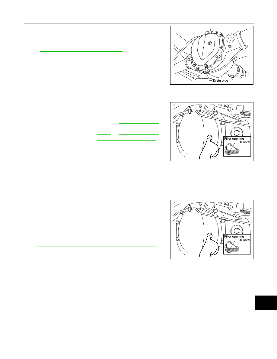
Remove the drain plug from the rear final drive assembly to
drain the differential gear oil.
3.
Install the drain plug with sealant applied on the threads to the
rear final drive assembly. Tighten to the specified torque. Refer
to
DLN-255, "Disassembly and Assembly"
.
• Use High Performance Thread Sealant or equivalent. Refer to
GI-22, "Recommended Chemical Products and Sealants"
FILLING
1.
Remove the filler plug from the rear final drive assembly.
2.
Fill the rear final drive assembly with new differential gear oil
until the level reaches the specified level near the filler plug hole.
3.
Install the filler plug with sealant applied on the threads to the
rear final drive assembly. Tighten to the specified torque. Refer
to
DLN-255, "Disassembly and Assembly"
.
• Use High Performance Thread Sealant or equivalent. Refer to
GI-22, "Recommended Chemical Products and Sealants"
DIFFERENTIAL GEAR OIL : Checking Differential Gear Oil
INFOID:0000000005612458
DIFFERENTIAL GEAR OIL LEAKAGE AND LEVEL
1.
Make sure that differential gear oil is not leaking from the rear final drive assembly or around it.
2.
Check the differential gear oil level from the filler plug hole as
shown.
CAUTION:
Do not start engine while checking differential gear oil level.
3.
Install the filler plug with sealant applied on the threads to the
rear final drive assembly. Tighten to the specified torque. Refer
to
DLN-255, "Disassembly and Assembly"
.
• Use High Performance Thread Sealant or equivalent. Refer to
GI-22, "Recommended Chemical Products and Sealants"
DIFFERENTIAL GEAR OIL : Rear Final Drive - M226 (ELD)
INFOID:0000000005272785
DIFFERENTIAL GEAR OIL : Changing Differential Gear Oil
INFOID:0000000005612453
DRAINING
1.
Stop engine.
LDIA0183E
Differential gear oil
grade and capacity
: Refer to
America: Fluids and Lubri-
cants"
or
.
LDIA0127E
LDIA0127E