Nissan Frontier D40. Manual - part 838


  Index      Nissan     Nissan Frontier D40 (2010 year) - Service and Repair Manual


Search            


Content   ..  836  837  838  839   ..


Nissan Frontier D40. Manual - part 838


ENGINE MAINTENANCE (VQ40DE)

MA-33

< ON-VEHICLE MAINTENANCE >

C

D

E

F

G

H

I

J

K

L

M

B

MA

N

O

A

CHECKING COOLING SYSTEM HOSES

Check hoses for the following:
• Improper attachment
• Leaks
• Cracks
• Damage
• Loose connections
• Chafing
• Deterioration

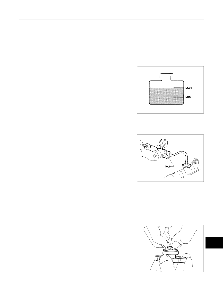
CHECKING RESERVOIR LEVEL

• Check if the engine coolant reservoir tank level is within MIN to

MAX when the engine is cool.

• Adjust engine coolant level as necessary.

CHECKING COOLING SYSTEM FOR LEAKS

WARNING:

Never remove the radiator/reservoir cap when the engine is hot. Serious burns could occur from high
pressure coolant escaping from the radiator or reservoir.
To check for leakage, apply pressure to the cooling system using
Tool.

CAUTION:

Higher pressure than specified may cause radiator damage.
NOTE:
In case that engine coolant decreases, replenish cooling system with
engine coolant.
If any concerns are found, repair or replace damaged parts.

CHECKING RESERVOIR CAP

1.

Inspect the reservoir cap.
• Replace the cap if the metal plunger cannot be seen around the edge of the black rubber gasket.
• Replace the cap if deposits of waxy residue or other foreign material are on the black rubber gasket or

the metal retainer.

NOTE:
Thoroughly wipe out the reservoir filler neck to remove any waxy residue or foreign material.

2.

Pull the negative-pressure valve to open it and check that it
closes completely when released.
• Check that there is no dirt or damage on the valve seat of the

reservoir cap negative-pressure valve.

• Check that there are no abnormalities in the opening and clos-

ing conditions of the negative-pressure valve.

SMA412B

Tool number

: EG17650301 (J-33984-A)

Testing pressure

: 137 kPa (1.4 kg/cm

2

, 20 psi)

WBIA0568E

SMA967B

MA-34

< ON-VEHICLE MAINTENANCE >

ENGINE MAINTENANCE (VQ40DE)

3.

Check reservoir cap relief pressure using suitable tool and Tool.

NOTE:
• Apply engine coolant to the cap seal surface. 
• Replace the reservoir cap if there is any damage in the nega-

tive-pressure valve, or if the open-valve pressure is outside of
the limit.

CHECKING RADIATOR CAP

Inspect the radiator cap.
NOTE:
Thoroughly wipe out the radiator filler neck to remove any waxy residue or foreign material.
• Replace the cap if the metal plunger cannot be seen around the edge of the black rubber gasket.
• Replace the cap if deposits of waxy residue or other foreign material are on the black rubber gasket or the

metal retainer.

CHECKING RADIATOR

Check radiator for mud or clogging. If necessary, clean radiator as follows.

CAUTION:

• Be careful not to bend or damage the radiator fins.
• When radiator is cleaned without removal, remove all surrounding parts such as cooling fan shroud

and horns. Then tape the harness and electrical connectors to prevent water from entering.

1.

Apply water by hose to the back side of the radiator core, with the hose pointed vertically downward.

2.

Apply water again to all radiator core surfaces once per minute.

3.

Stop washing if any stains no longer flow out from the radiator.

4.

Blow air into the back side of radiator core, with the air hose pointed vertically downward.
• Use compressed air lower than 490 kPa (5 kg/cm

2

, 71 psi) and keep distance more than 30 cm (11.8 in). 

5.

Blow air again into all the radiator core surfaces once per minute until no water sprays out.

6.

Check for leaks.

ENGINE COOLANT : Changing Engine Coolant

INFOID:0000000005272752

WARNING:

• To avoid being scalded, never change the coolant when the engine is hot.
• Wrap a thick cloth around the cap to carefully remove the cap. First, turn the cap a quarter of a turn

to release any built-up pressure, then push down and turn the cap all the way to remove it.

DRAINING ENGINE COOLANT

1.

Turn ignition switch ON and set temperature control lever all the way to HOT position or the highest tem-
perature position. Wait 10 seconds and turn ignition switch OFF.

2.

Remove the engine front undercover. Refer to 

EXT-13, "Removal and Installation"

.

3.

Open the radiator drain plug at the bottom of the radiator, and
remove the reservoir cap. This is the only step required when
partially draining the cooling system (radiator only). 

CAUTION:

Do not allow the coolant to contact the drive belts. 

Tool number

: EG17650301 (J-33984-A)

Standard: 98 – 118 kPa (1.0 – 1.2 kg/cm

2

, 14 – 17 psi)

Limit: 59 kPa (0.6 kg/cm

2

, 9 psi)

WBIA0570E

LLIA0070E

ENGINE MAINTENANCE (VQ40DE)

MA-35

< ON-VEHICLE MAINTENANCE >

C

D

E

F

G

H

I

J

K

L

M

B

MA

N

O

A

4.

When draining all of the coolant in the system for engine
removal or repair, it is necessary to drain the cylinder block.
Remove the cylinder block drain plugs (A), (B), (C), (D) and
block heater if equipped, to drain the cylinder block as shown.
NOTE:
For Canada, the (D) cylinder block drain plug as shown, is not a
cylinder block drain plug but a block heater.

5.

Remove the reservoir tank to drain the engine coolant, then clean the reservoir tank before installing it.

6.

Check the drained coolant for contaminants such as rust, corrosion or discoloration.
If the coolant is contaminated, flush the engine cooling system. Follow the "Flushing Cooling System" pro-
cedure.

REFILLING ENGINE COOLANT

1.

Close the radiator drain plug. Install the reservoir tank, cylinder
block drain plugs (A), (B), (C), (D) and block heater if equipped,
if removed for a total system drain or for engine removal or
repair.
• The radiator must be completely empty of coolant and water.
• Apply sealant to the threads of the cylinder block drain plugs

(A), (B), (C), (D). Use Genuine High Performance Thread
Sealant or equivalent. Refer to 

GI-22, "Recommended Chemi-

cal Products and Sealants"

.

• Tighten each plug to the specified torque. Refer to 

EM-215,

"Disassembly and Assembly"

.

2.

Set the vehicle heater controls to the full HOT and heater ON position. Turn the vehicle ignition ON with
the engine OFF as necessary to activate the heater mode.

3.

Remove the vented reservoir cap and replace it with a non-vented reservoir cap before filling the cooling
system.

WLIA0020E

WLIA0020E

MA-36

< ON-VEHICLE MAINTENANCE >

ENGINE MAINTENANCE (VQ40DE)

4.

Install the Tool by installing the radiator cap adapter onto the
radiator neck opening. Then attach the gauge body assembly
with the refill tube and the venturi assembly to the radiator cap
adapter.

5.

Insert the refill hose into the coolant mixture container that is
placed at floor level. Make sure the ball valve is in the closed
position. 
• Use recommended coolant or equivalent.

Refer to 

MA-16, "For North America: Fluids and Lubricants"

.

6.

Install an air hose to the venturi assembly, the air pressure must
be within specification. 

CAUTION:

The compressed air supply must be equipped with an air dryer.

7.

The vacuum gauge will begin to rise and there will be an audible hissing noise. During this process open
the ball valve on the refill hose slightly. Coolant will be visible rising in the refill hose. Once the refill hose is
full of coolant, close the ball valve. This will purge any air trapped in the refill hose.

8.

Continue to draw the vacuum until the gauge reaches 28 inches
of vacuum. The gauge may not reach 28 inches in high altitude
locations, use the vacuum specifications based on the altitude
above sea level.

9.

When the vacuum gauge has reached the specified amount, disconnect the air hose and wait 20 seconds
to see if the system loses any vacuum. If the vacuum level drops, perform any necessary repairs to the
system and repeat steps 6 - 8 to bring the vacuum to the specified amount. Recheck for any leaks. 

10. Place the coolant container (with the refill hose inserted) at the same level as the top of the radiator. Then

open the ball valve on the refill hose so the coolant will be drawn up to fill the cooling system. The cooling
system is full when the vacuum gauge reads zero.

CAUTION:

Do not allow the coolant container to get too low when filling, to avoid air from being drawn into
the cooling system. 

11. Remove the Tool from the radiator neck opening and install the radiator cap.

12. Remove the non-vented reservoir cap.

13. Fill the cooling system reservoir tank to the specified level. Run the engine to warm up the cooling system

and top up the system as necessary before installing the vented reservoir cap.

FLUSHING COOLING SYSTEM

1.

Drain the water from the engine cooling system. Refer to 

MA-34, "ENGINE COOLANT : Changing Engine

Coolant"

.

Tool number

: KV991J0070 (J-45695)

Cooling system capacity 
(with reservoir)

: Refer to 

MA-16, "For 

North America: Fluids and 
Lubricants"

.

Compressed air 
supply pressure

: 549 - 824 kPa (5.6 - 8.4 kg/cm

2

80 - 120 psi)

LLIA0058E

Altitude above sea level

Vacuum gauge reading

0 - 100 m (328 ft)

: 28 inches of vacuum

300 m (984 ft)

: 27 inches of vacuum

500 m (1,641 ft)

: 26 inches of vacuum

1,000 m (3,281 ft)

: 24 - 25 inches of vacuum

LLIA0057E


Content   ..  836  837  838  839   ..