Nissan Frontier D40. Manual - part 823


  Index      Nissan     Nissan Frontier D40 (2010 year) - Service and Repair Manual


Search            


Content   ..  821  822  823  824   ..


Nissan Frontier D40. Manual - part 823


PRECAUTIONS

LU-3

< PRECAUTION >

[QR25DE]

C

D

E

F

G

H

I

J

K

L

M

A

LU

N

P

O

PRECAUTION

PRECAUTIONS

Precaution for Supplemental Restraint System (SRS) "AIR BAG" and "SEAT BELT 
PRE-TENSIONER"

INFOID:0000000005575330

The Supplemental Restraint System such as “AIR BAG” and “SEAT BELT PRE-TENSIONER”, used along
with a front seat belt, helps to reduce the risk or severity of injury to the driver and front passenger for certain
types of collision. This system includes seat belt switch inputs and dual stage front air bag modules. The SRS
system uses the seat belt switches to determine the front air bag deployment, and may only deploy one front
air bag, depending on the severity of a collision and whether the front occupants are belted or unbelted.
Information necessary to service the system safely is included in the SR and SB section of this Service Man-
ual.

WARNING:

• To avoid rendering the SRS inoperative, which could increase the risk of personal injury or death in

the event of a collision which would result in air bag inflation, all maintenance must be performed by
an authorized NISSAN/INFINITI dealer.

• Improper maintenance, including incorrect removal and installation of the SRS, can lead to personal

injury caused by unintentional activation of the system. For removal of Spiral Cable and Air Bag
Module, see the SR section.

• Do not use electrical test equipment on any circuit related to the SRS unless instructed to in this

Service Manual. SRS wiring harnesses can be identified by yellow and/or orange harnesses or har-
ness connectors.

PRECAUTIONS WHEN USING POWER TOOLS (AIR OR ELECTRIC) AND HAMMERS

WARNING:

• When working near the Airbag Diagnosis Sensor Unit or other Airbag System sensors with the Igni-

tion ON or engine running, DO NOT use air or electric power tools or strike near the sensor(s) with a
hammer. Heavy vibration could activate the sensor(s) and deploy the air bag(s), possibly causing
serious injury.

• When using air or electric power tools or hammers, always switch the Ignition OFF, disconnect the

battery, and wait at least 3 minutes before performing any service.

Precaution for Liquid Gasket

INFOID:0000000005272512

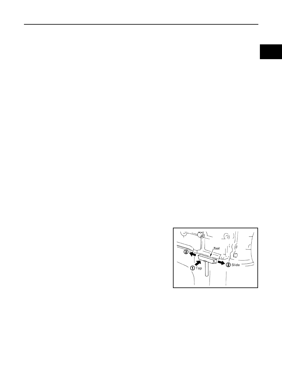
REMOVAL OF LIQUID GASKET SEALING

• After removing the bolts and nuts, separate the mating surface and

remove the old liquid gasket sealing using Tool.

CAUTION:

Do not damage the mating surfaces.

• Tap (1) the Tool to insert it.
• In areas where the Tool is difficult to use, lightly tap to slide (2) it.

LIQUID GASKET APPLICATION PROCEDURE

Tool number

: KV10111100 (J-37228)

WBIA0566E

LU-4

< PRECAUTION >

[QR25DE]

PRECAUTIONS

1.

Remove the old liquid gasket adhering to the gasket application
surface and the mating surface using suitable tool.
• Remove the liquid gasket completely from the groove of the

liquid gasket application surface, bolts, and bolt holes.

2.

Thoroughly clean the mating surfaces and remove adhering
moisture, grease and foreign material.

3.

Attach the liquid gasket tube to the Tool.

Use Genuine RTV Silicone Sealant or equivalent. Refer to

GI-22, "Recommended Chemical Products and Sealants"

4.

Apply the liquid gasket without breaks to the specified location
with the specified dimensions.

• If there is a groove for the liquid gasket application, apply the

liquid gasket to the groove.

• As for the bolt holes, normally apply the liquid gasket inside

the holes. If specified in the procedure, it should also be
applied outside the holes.

• Within five minutes of liquid gasket application, install the mat-

ing component.

• If the liquid gasket protrudes, wipe it off immediately.
• Do not retighten after the installation.
• Wait 30 minutes or more after installation before refilling the

engine with engine oil and engine coolant.

CAUTION:

If there are specific instructions in this manual, observe them.

PBIC0003E

Tool number

: WS39930000 (

)

WBIA0567E

SEM159F

PREPARATION

LU-5

< PREPARATION >

[QR25DE]

C

D

E

F

G

H

I

J

K

L

M

A

LU

N

P

O

PREPARATION

PREPARATION

Special Service Tool

INFOID:0000000005272513

The actual shapes of Kent-Moore tools may differ from those of special service tools illustrated here.

Commercial Service Tool

INFOID:0000000005272514

Tool number
(Kent-Moore No.)
Tool name

Description

ST25051001
(J-25695-1)
Oil pressure gauge

Measuring oil pressure
Maximum measuring range:

2,452 kPa (25 kg/cm

2

, 356 psi)

ST25052000
(J-25695-2)
Hose

Adapting oil pressure gauge to oil pan (upper)

KV10111100
(J-37228)
Seal cutter

Removing oil pan and front cover, etc.

KV10115801
(J-38956)
Oil filter wrench

Removing and installing oil filter
a: 64.3 mm (2.531 in)

WS39930000
(

)

Tube presser 

Pressing the tube of liquid gasket

NT050

S-NT559

S-NT046

S-NT375

NT052

LU-6

< PREPARATION >

[QR25DE]

PREPARATION

Tool name

Description

Power tool

Loosening nuts and bolts

Deep socket

Removing and installing oil pressure switch
a: 24 mm (0.94 in)

PBIC0190E

PBIC2072E


Content   ..  821  822  823  824   ..