Nissan Frontier D40. Manual - part 803
CENTER CONSOLE ASSEMBLY
IP-19
< DISASSEMBLY AND ASSEMBLY >
C
D
E
F
G
H
I
K
L
M
A
B
IP
N
O
P
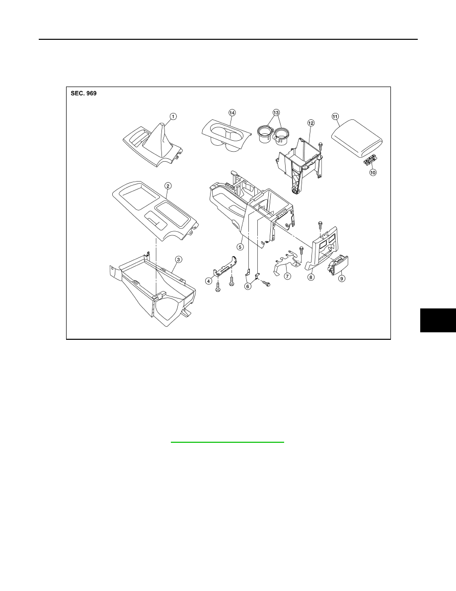
CENTER CONSOLE ASSEMBLY
Exploded View
INFOID:0000000005272877
Disassembly and Assembly
INFOID:0000000005272878
DISASSEMBLY
1.
Remove center console. Refer to
IP-11, "Removal and Installation"
2.
Remove center console lid.
3.
Remove latch from center console lid.
4.
Remove hinge from center console lid.
5.
Remove rear finisher assembly.
6.
Remove rear cup holder assembly.
7.
Remove brackets.
8.
Disconnect center console harness connectors.
9.
Remove cup holder insert and cup holder finisher.
10. Remove center console bin.
11. Remove center console bracket.
12. Remove wire harness bracket.
AWJIA0412ZZ
1.
M/T finisher
2.
A/T finisher
3.
Center console front base
4.
Bracket
5.
Center console rear base
6.
Bracket
7.
Wire harness bracket
8.
Rear finisher assembly
9.
Rear cup holder assembly
10.
Hinge
11.
Center console lid
12.
Center console bin
13.
Cup holder insert
14.
Cup holder finisher
A.
Bolt