Nissan Frontier D40. Manual - part 763
INTERIOR ROOM LAMP CONTROL SYSTEM
INL-7
< FUNCTION DIAGNOSIS >
[WITH POWER DOOR LOCKS]
C
D
E
F
G
H
I
J
K
M
A
B
INL
N
O
P
If an interior lamp is left ON and does not turn OFF even when the doors are closed, the BCM turns off power
to the interior lamps automatically to save the battery 30 minutes after the ignition switch is turned OFF.
The BCM controls power and ground to all interior lamps.
After the battery saver system turns the lamps OFF, the lamps will illuminate again when
• a signal is received from a main power window and door lock/unlock switch, or when the front door lock
assembly LH (key cylinder switch) is locked or unlocked
• a door is opened or closed
The interior lamp battery saver control time period can be changed with the function setting of CONSULT-III.
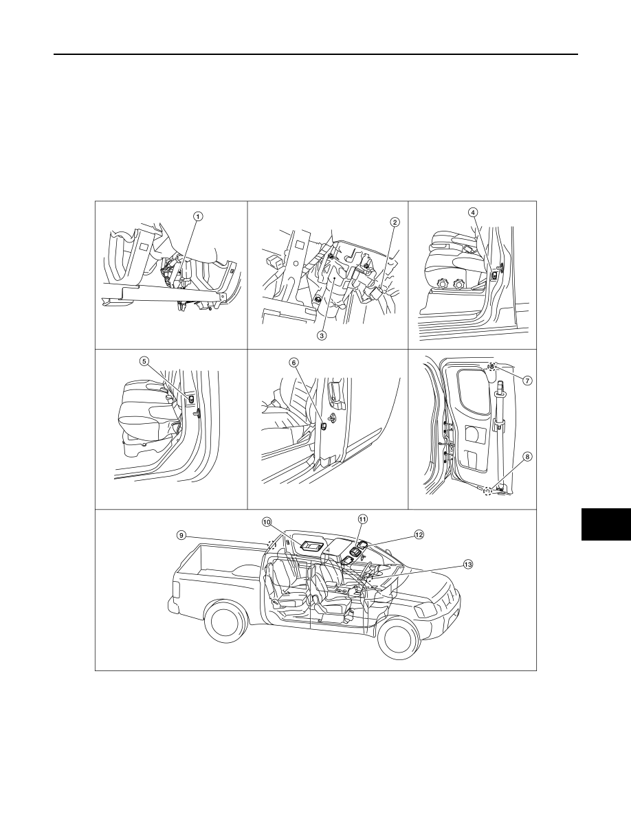
Component Parts Location
INFOID:0000000005272801
1.
BCM M18, M19, M20 (view with lower
instrument panel LH removed)
2.
Key switch M27
3.
Steering column assembly
4.
Front door switch LH B8 (crew cab)
Front door switch RH B108 (crew cab)
5.
Rear door switch LH B18 (crew cab)
Rear door switch RH B116 (crew cab)
6.
Front door switch LH D213 (king cab)
Front door switch RH D316 (king cab)
7.
Rear door switch upper LH D211 (king
cab)
Rear door switch upper LH D312 (king
cab)
8.
Rear door switch lower LH D212 (king
cab)
Rear door switch lower LH D313 (king
cab)
9.
Cargo lamp B161
WKIA5028E