Nissan Frontier D40. Manual - part 619


  Index      Nissan     Nissan Frontier D40 (2010 year) - Service and Repair Manual


Search            


Content   ..  617  618  619  620   ..


Nissan Frontier D40. Manual - part 619


EM-208

< ON-VEHICLE REPAIR >

[VQ40DE]

CYLINDER HEAD

2.

Ream cylinder head recess diameter for service valve seat.

• Be sure to ream in circles concentric to valve guide center.

This will enable valve to fit correctly.

3.

Heat cylinder head to 110

°

 to 130

°

C (230

°

 to 266

°

F) by soaking

in heated oil.

4.

Provide valve seats cooled well with dry ice. Force fit valve seat into cylinder head.

WARNING:

• Cylinder head contains heat. When working, wear protective equipment to avoid getting burned.

CAUTION:

• Avoid directly touching cold valve seats.

5.

Finish seat to the specified dimensions using suitable tool. Refer
to 

EM-242, "Standard and Limit"

.

CAUTION:

When using valve seat cutter, firmly grip cutter handle with
both hands. Then, press on the contacting surface all
around the circumference to cut in a single drive. Improper
pressure on with cutter or cutting many different times may
result in staged valve seat. 

6.

Using compound, grind to adjust valve fitting. 

7.

Check again for normal contact.

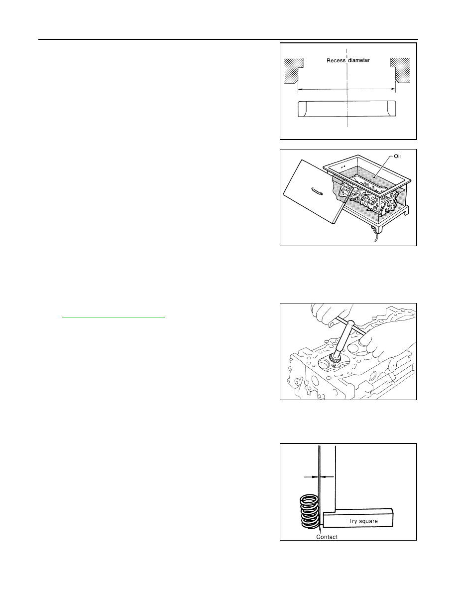
VALVE SPRING SQUARENESS

• Set try square along the side of valve spring and rotate spring.

Measure the maximum clearance between the top face of spring
and try square.

• If it exceeds the limit, replace valve spring.

VALVE SPRING DIMENSIONS AND VALVE SPRING PRESSURE LOAD

Oversize [0.5 mm (0.020 in)]

Intake

: 38.500 - 38.516 mm (1.5157 - 1.5164 in)

Exhaust

: 32.700 - 32.716 mm (1.2874 - 1.2880 in)

SEM795A

SEM008A

SEM934C

Limit

: 2.1 mm (0.083 in)

PBIC0080E

CYLINDER HEAD

EM-209

< ON-VEHICLE REPAIR >

[VQ40DE]

C

D

E

F

G

H

I

J

K

L

M

A

EM

N

P

O

• Check valve spring pressure at the specified spring height.

• If the installation load or load with valve open is out of the standard, replace valve spring.

Standard:

Intake and exhaust

Free height

: 47.07 mm (1.8531 in)

Installation height

: 37.00 mm (1.4567 in)

Installation load

: 166 - 188 N (16.9 - 19.2 kg, 37 - 42 lb)

Height during valve open

: 27.20 mm (1.0709 in)

Load with valve open

: 373 - 421 N (38.0 - 42.9 kg, 84 - 95 lb)

SEM113

EM-210

< REMOVAL AND INSTALLATION >

[VQ40DE]

ENGINE ASSEMBLY

REMOVAL AND INSTALLATION

ENGINE ASSEMBLY

Exploded View

INFOID:0000000005274356

Removal and Installation

INFOID:0000000005274357

WARNING:

• Situate vehicle on a flat and solid surface.
• Place chocks at front and back of rear wheels.
• For engines not equipped with engine slingers, attach proper slingers and bolts described in PARTS

CATALOG.

1.

Rear engine mounting insulator 4WD

2. Rear engine mounting insulator 2WD

3.

LH engine mounting bracket (upper)

4.

LH heat shield plate

5. LH engine mounting insulator

6.

LH engine mounting bracket (lower)

7.

RH engine mounting bracket (lower)

8. RH engine mounting insulator

9.

RH heat shield plate

10. RH engine mounting bracket (upper)

AWBIA0721GB

ENGINE ASSEMBLY

EM-211

< REMOVAL AND INSTALLATION >

[VQ40DE]

C

D

E

F

G

H

I

J

K

L

M

A

EM

N

P

O

CAUTION:

• Always be careful to work safely, avoid forceful or uninstructed operations.
• Do not start working until exhaust system and engine coolant are cooled sufficiently.
• If items or work required are not covered by the engine section, follow the procedures in the applica-

ble sections.

• Always use the support point specified for lifting.
• Use either 2-point lift type or separate type lift. If board-on type is used for unavoidable reasons,

support at the rear axle jacking point with transmission jack or similar tool before starting work, in
preparation for the backward shift of center of gravity.

• For supporting points for lifting and jacking point at rear axle, refer to 

GI-38, "Garage Jack and

Safety Stand"

.

REMOVAL

Preparation

1.

Remove front and rear engine under covers, if equipped. Refer to 

EXT-13, "Removal and Installation"

.

2.

Drain engine oil. Refer to 

LU-22, "Changing Engine Oil"

.

3.

Remove engine oil filter.

4.

Drain engine coolant. Refer to 

CO-39, "Changing Engine Coolant"

.

5.

Partially drain A/T fluid. Refer to 

TM-263, "Changing the A/T Fluid (ATF)"

.

6.

Remove the front wheels and tires. Refer to 

WT-46, "Rotation"

.

7.

Remove the front fender protectors. Refer to 

EXT-20, "Removal and Installation"

.

8.

Release fuel pressure. Refer to 

EC-954, "Fuel Pressure Check"

.

9.

Remove the engine hood. Refer to 

DLK-127, "Removal and Installation of Hood Assembly"

.

10. Disconnect the battery negative terminal. Refer to 

PG-84, "Removal and Installation"

.

11. Remove engine room cover. Refer to 

EM-138, "Removal and Installation"

.

12. Remove the air duct and resonator assembly and air cleaner case assembly. Refer to 

EM-139, "Removal

and Installation"

.

13. Disconnect vacuum hose between vehicle and engine and set it aside.

14. Remove the radiator assembly and hoses. Refer to 

CO-43, "Removal and Installation"

.

15. Remove the drive belt. Refer to 

EM-127, "Removal and Installation"

16. Remove the engine cooling fan. Refer to 

CO-46, "Removal and Installation (Crankshaft driven type)"

.

17. Disconnect the engine room harness from the engine side and set it aside.
18. Disconnect the engine harness grounds.

19. Disconnect the reservoir tank for power steering from engine and move it aside.

20. Disconnect power steering oil pump from engine. Move it from its location and secure with a rope. Refer to

ST-18, "Removal and Installation"

21. Remove the A/C compressor bolts and set aside. Refer to 

HA-28, "Removal and Installation for Compres-

sor"

.

22. Disconnect brake booster vacuum line.

23. Disconnect EVAP line.

24. Disconnect the fuel hose at the engine side connection. Refer to 

EM-159, "Removal and Installation"

.

25. Disconnect the heater hoses at cowl, and install plugs to avoid leakage of engine coolant.

26. Remove the A/T oil level indicator and indicator tube.

27. Remove front final drive assembly (4WD models). Refer to 

DLN-190, "Removal and Installation"

.

28. Remove three way catalyst. Refer to 

EM-145, "Removal and Installation (Three Way Catalyst)"

.


Content   ..  617  618  619  620   ..