Nissan Frontier D40. Manual - part 610


  Index      Nissan     Nissan Frontier D40 (2010 year) - Service and Repair Manual


Search            


Content   ..  608  609  610  611   ..


Nissan Frontier D40. Manual - part 610


EM-172

< ON-VEHICLE REPAIR >

[VQ40DE]

FRONT TIMING CHAIN CASE
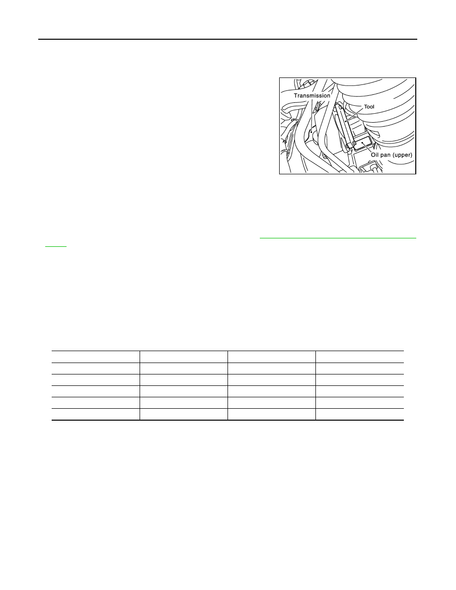
c.

Remove Tool. 

9.

Rotate crankshaft pulley in normal direction (clockwise when viewed from front) to confirm it turns
smoothly.

10. Installation of the remaining components is in the reverse order of removal.

INSPECTION AFTER INSTALLATION

• Before starting the engine, check oil/fluid levels including engine coolant and engine oil. If the levels are

lower than required quantity, fill to the specified level. Refer to 

MA-16, "For North America: Fluids and Lubri-

cants"

.

• Run engine to check for unusual noise and vibration.

NOTE:
If hydraulic pressure inside timing chain tensioner drops after removal and installation, slack in the guide
may generate a pounding noise during and just after engine start. However, this is normal. Noise will stop
after hydraulic pressure rises.

• Warm up engine thoroughly to make sure there is no leakage of fuel, exhaust gas, or any oil/fluids including

engine oil and engine coolant.

• Bleed air from passages in lines and hoses, such as in cooling system.
• After cooling down the engine, again check oil/fluid levels including engine oil and engine coolant. Refill to

specified level if necessary.

• Summary of the inspection items:

* Transmission/transaxle/CVT fluid, power steering fluid, brake fluid, etc.

Step 1

: 44.1 N·m (4.5 kg-m, 33 ft-lb)

Step 2

: 84

°

 - 90

°

 degrees clockwise

Tool number

:   —   (J-48761)

WBIA0580E

Item

Before starting engine

Engine running

After engine stopped

Engine coolant

Level

Leakage

Level

Engine oil

Level

Leakage

Level

Other oils and fluids*

Level

Leakage

Level

Fuel

Leakage

Leakage

Leakage

Exhaust gas

Leakage

TIMING CHAIN

EM-173

< ON-VEHICLE REPAIR >

[VQ40DE]

C

D

E

F

G

H

I

J

K

L

M

A

EM

N

P

O

TIMING CHAIN

Exploded View

INFOID:0000000005274344

Removal and Installation

INFOID:0000000005274345

CAUTION:

• After removing timing chains, do not turn the crankshaft and camshaft separately, or the valves will

strike the pistons.

• When installing camshafts, chain tensioners, oil seals, or other sliding parts, lubricate contacting

surfaces with new engine oil.

• Apply new engine oil to bolt threads and seat surfaces when installing camshaft sprockets, camshaft

brackets, and crankshaft pulley.

REMOVAL

1.

Remove front timing chain case. Refer to 

EM-164, "Removal and Installation"

.

2.

Remove timing chain tensioner (primary) as follows:

AWBIA0859GB

1.

Internal chain guide

2.

O-ring

3.

Timing chain tensioner (secondary) (RH)

4.

Camshaft sprocket (EXH)

5.

Timing chain (secondary)

6.

Timing chain (primary)

7.

Camshaft sprocket RH (INT)

8.

Camshaft sprocket LH (INT)

9.

Slack guide

10.

Timing chain tensioner (primary)

11.

Crankshaft sprocket

12.

Timing chain tensioner (secondary) (LH)

13.

O-ring

14.

Tension guide

EM-174

< ON-VEHICLE REPAIR >

[VQ40DE]

TIMING CHAIN

a.

Loosen clip of timing chain tensioner (primary), and release
plunger stopper (1).

b.

Insert plunger into tensioner body by pressing slack guide (2).

c.

Keep slack guide pressed and hold plunger in by pushing stop-
per pin through the tensioner body hole and plunger groove (3).

d.

Remove bolts and remove timing chain tensioner (primary).

3.

Remove internal chain guide, tension guide and slack guide.
NOTE:
Tension guide can be removed after removing timing chain (pri-
mary).

4.

Remove timing chain (primary).

CAUTION:

After removing timing chain (primary), do not turn crankshaft and camshaft separately, or valves
will strike the piston heads.

5.

Remove crankshaft sprocket, if necessary.

6.

Remove timing chain (secondary) and camshaft sprockets as follows:

a.

Attach suitable stopper pin to the right and left timing chain ten-
sioners (secondary).
NOTE:
• Use approximately 0.5 mm (0.02 in) dia. hard metal pin as a

stopper pin.

• For removal of timing chain tensioner (secondary), refer to

EM-186

. [Removing camshaft bracket (No. 1) is required.]

PBIC2919E

PBIC2266E

PBIC2047E

TIMING CHAIN

EM-175

< ON-VEHICLE REPAIR >

[VQ40DE]

C

D

E

F

G

H

I

J

K

L

M

A

EM

N

P

O

b.

Remove camshaft sprocket (INT and EXH) bolts.
• Secure the hexagonal portion of camshaft using wrench to

loosen bolts.

CAUTION:

Do not loosen bolts by securing anything other than the
camshaft hexagonal portion.

c.

Remove timing chain (secondary) together with camshaft sprockets.
• Turn camshaft slightly to secure slackness of timing chain on timing chain tensioner (secondary) side.
• Insert 0.5 mm (0.020 in)-thick metal or resin plate between tim-

ing chain and timing chain tensioner plunger (guide). Remove
timing chain (secondary) together with camshaft sprockets
with timing chain loose from guide groove.

CAUTION:

Be careful of plunger coming off when removing timing
chain (secondary). 
NOTE:
Camshaft sprocket (INT) is a one piece integrated design
sprockets for timing chain (primary) and for timing chain (sec-
ondary).

• When handling camshaft sprocket (INT), be careful of the fol-

lowing:

CAUTION:

• Handle carefully to avoid any shock to camshaft

sprocket.

• Do not disassemble. (Do not loosen bolts (A) as shown).

7.

Remove timing chain tensioners (secondary) from cylinder head if necessary.

a.

Remove camshaft brackets (No. 1). Refer to 

EM-187, "Removal and Installation"

.

b.

Remove timing chain tensioners (secondary) with stopper pin attached.

INSPECTION AFTER REMOVAL

Check for cracks and any excessive wear at link plates. Replace
chain if necessary.
• In the same way as for the LH bank, inspect the timing chain and

associated parts on the RH bank.

KBIA1698J

PBIC1978E

PBIC2920E

PBIC0282E


Content   ..  608  609  610  611   ..