Nissan Frontier D40. Manual - part 544


  Index      Nissan     Nissan Frontier D40 (2010 year) - Service and Repair Manual


Search            


Content   ..  542  543  544  545   ..


Nissan Frontier D40. Manual - part 544


IGNITION SIGNAL

EC-867

< COMPONENT DIAGNOSIS >

[VQ40DE]

C

D

E

F

G

H

I

J

K

L

M

A

EC

N

P

O

1.

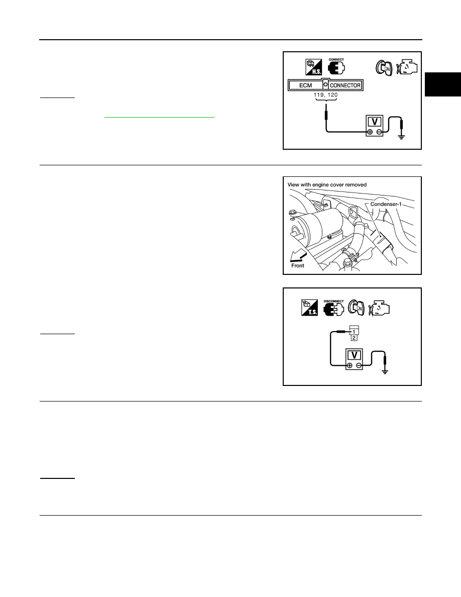
Turn ignition switch OFF, wait at least 10 seconds and then turn it ON.

2.

Check voltage between ECM terminals 119, 120 and ground
with CONSULT-III or tester.

OK or NG

OK

>> GO TO 5.

NG

>> Go to 

EC-546, "Diagnosis Procedure"

.

5.

CHECK IGNITION COIL POWER SUPPLY CIRCUIT-II

1.

Turn ignition switch OFF.

2.

Disconnect condenser-1 harness connector.

3.

Turn ignition switch ON.

4.

Check voltage between condenser-1 terminal 1 and ground with
CONSULT-III or tester.

OK or NG

OK

>> GO TO 8.

NG

>> GO TO 6.

6.

CHECK IGNITION COIL POWER SUPPLY CIRCUIT-III

1.

Turn ignition switch OFF.

2.

Disconnect IPDM E/R harness connector E119.

3.

Check harness continuity between IPDM E/R terminal 3 and condenser-1 terminal 1.
Refer to Wiring Diagram.

4.

Also check harness for short to ground and short to power.

OK or NG

OK

>> GO TO 17.

NG

>> GO TO 7.

7.

DETECT MALFUNCTIONING PART

Check the following.
• Harness connectors E2, F32
• Harness for open or short between condenser-1 and IPDM E/R

>> Repair open circuit or short to ground or short to power in harness or connectors.

Voltage: Battery voltage

MBIB0034E

BBIA0562E

Voltage: Battery voltage

PBIB0624E

Continuity should exist.

EC-868

< COMPONENT DIAGNOSIS >

[VQ40DE]

IGNITION SIGNAL

8.

CHECK CONDENSER-1 GROUND CIRCUIT FOR OPEN AND SHORT

1.

Turn ignition switch OFF.

2.

Check harness continuity between condenser-1 terminal 2 and ground.
Refer to Wiring Diagram.

3.

Also check harness for short to power.

OK or NG

OK

>> GO TO 9.

NG

>> Repair open circuit or short to power in harness or connectors.

9.

CHECK CONDENSER-1

Refer to 

EC-869, "Component Inspection"

.

OK or NG

OK

>> GO TO 10.

NG

>> Replace condenser-1.

10.

CHECK IGNITION COIL POWER SUPPLY CIRCUIT-V

1.

Turn ignition switch OFF.

2.

Reconnect all harness connectors disconnected.

3.

Disconnect ignition coil harness connector.

4.

Turn ignition switch ON.

5.

Check voltage between ignition coil terminal 3 and ground with
CONSULT-III or tester.

OK or NG

OK

>> GO TO 12.

NG

>> GO TO 11.

11.

DETECT MALFUNCTIONING PART

Check the following.
• Harness connectors F26, F225
• Harness for open or short between ignition coil and harness connector F32

>> Repair or replace harness or connectors.

12.

CHECK IGNITION COIL GROUND CIRCUIT FOR OPEN AND SHORT

1.

Turn ignition switch OFF.

2.

Check harness continuity between ignition coil terminal 2 and ground.
Refer to Wiring Diagram.

Continuity should exist.

Voltage: Battery voltage

BBIA0561E

PBIB0138E

Continuity should exist.

IGNITION SIGNAL

EC-869

< COMPONENT DIAGNOSIS >

[VQ40DE]

C

D

E

F

G

H

I

J

K

L

M

A

EC

N

P

O

3.

Also check harness for short to power.

OK or NG

OK

>> GO TO 14.

NG

>> GO TO 13.

13.

DETECT MALFUNCTIONING PART

Check the following.
• Harness connectors F225, F26
• Harness for open or short between ignition coil and ground

>> Repair open circuit or short to power in harness or connectors.

14.

CHECK IGNITION COIL OUTPUT SIGNAL CIRCUIT FOR OPEN AND SHORT

1.

Disconnect ECM harness connector.

2.

Check harness continuity between ECM terminals 60, 61, 62, 79, 80, 81 and ignition coil terminal 1.
Refer to Wiring Diagram.

3.

Also check harness for short to ground and short to power.

OK or NG

OK

>> GO TO 16.

NG

>> GO TO 15.

15.

DETECT MALFUNCTIONING PART

Check the following.
• Harness connectors F26, F225
• Harness for open or short between ignition coil and ECM

>> Repair open circuit or short to ground or short to power in harness or connectors.

16.

CHECK IGNITION COIL WITH POWER TRANSISTOR

Refer to 

EC-869, "Component Inspection"

.

OK or NG

OK

>> GO TO 17.

NG

>> Replace malfunctioning ignition coil with power transistor.

17.

CHECK INTERMITTENT INCIDENT

Refer to 

GI-46, "Intermittent Incident"

.

>> INSPECTION END

Component Inspection

INFOID:0000000005273884

IGNITION COIL WITH POWER TRANSISTOR

CAUTION:

Do the following procedure in the place where ventilation is good without the combustible.
1.

Turn ignition switch OFF.

2.

Disconnect ignition coil harness connector.

Continuity should exist.

EC-870

< COMPONENT DIAGNOSIS >

[VQ40DE]

IGNITION SIGNAL

3.

Check resistance between ignition coil terminals as follows.

4.

If NG, Replace ignition coil with power transistor.
If OK, go to next step.

5.

Turn ignition switch OFF.

6.

Reconnect all harness connectors disconnected.

7.

Remove fuel pump fuse (No.48) in IPDM E/R to release fuel
pressure.
NOTE:
Do not use CONSULT-III to release fuel pressure, or fuel pres-
sure applies again during the following procedure.

8.

Start engine.

9.

After engine stalls, crank it two or three times to release all fuel
pressure.

10. Turn ignition switch OFF.
11. Remove ignition coil harness connectors to avoid the electrical

discharge from the ignition coils.

12. Remove ignition coil and spark plug of the cylinder to be

checked.

13. Crank engine for five seconds or more to remove combustion gas in the cylinder.
14. Connect spark plug and harness connector to ignition coil.
15. Fix ignition coil using a rope etc. with gap of 13 - 17 mm (0.52 -

0.66 in) between the edge of the spark plug and grounded metal
portion as shown in the figure.

16. Crank engine for about three seconds, and check whether spark

is generated between the spark plug and the grounded part.

CAUTION:

• Never place to the spark plug and the ignition coil within

50cm (19.7 in) each other. Be careful not to get an electri-
cal shock while checking, because the electrical dis-
charge voltage becomes 20 kV or more.

• It might cause to damage the ignition coil if the gap of more than 17 mm (0.66 in) is made.
NOTE:
When the gap is less than 13 mm (0.52 in), the spark might be generated even if the coil is mal-
functioning.

17. If NG, Replace ignition coil with power transistor.

CONDENSER-1

1.

Turn ignition switch OFF.

2.

Disconnect condenser-1 harness connector.

3.

Check resistance between condenser-1 terminals 1 and 2.

Terminal No. (Polarity)

Resistance 

 [at 25

°

C (77

°

F)]

1 and 2

Except 0 or 

1 and 3

Except 0

2 and 3

Spark should be generated.

PBIB0847E

BBIA0534E

JMBIA0066GB

Resistance

Above 1 M

 at 25

°

C (77

°

F)

PBIB0794E


Content   ..  542  543  544  545   ..